Lesson 15 Driving Dot-Matrix by 74HC595
Introduction
As the name suggests, an LED dot matrix is a matrix composed of LEDs. The lighting up and dimming of the LEDs formulate different characters and patterns.
Components
- 1 * Raspberry Pi
- 1 * Breadboard
- 2 * 74HC595
- 1 * Dot-Matrix
- Jumper wires
- 1 * T-Extension Board
- 1 * 40-Pin GPIO Cable
Principle
Dot Matrix
Generally, dot matrix can be categorized into two types: common cathode (CC) and common anode (CA). They look much alike, but internally the difference lies. You can tell by test. A CA one is used in this kit. You can see 788BS labeled at the side.
See the figure below. The pins are arranged at the two ends at the back. Take the label side for reference: pins on this end are pin 1-8, and oh the other are pin 9-16.
The external view:
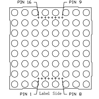
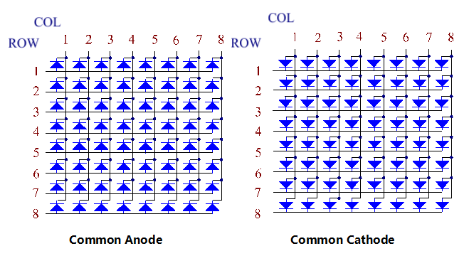
Below the figures show their internal structure. You can see in a CA matrix, ROW represents the anode of the LED, and COL is cathode; it’s contrary for a CC one. One thing in common: for both types, pin 13, 3, 4, 10, 6, 11, 15, and 16 are all COL, when pin 9, 14, 8, 12, 1, 7, 2, and 5 are all ROW. If you want to turn on the first LED at the top left corner, for a CA matrix, just set pin 9 as High and pin 13 as Low, and for a CC one, set pin 13 as High and pin 9 as Low. If you want to light up the whole first column, for CA, set pin 13 as Low and ROW 9, 14, 8, 12, 1, 7, 2, and 5 as High, when for CC, set pin 13 as High and ROW 9, 14, 8, 12, 1, 7, 2, and 5 as Low. Consider the following figures for better understanding.
The internal view:
Pin numbering corresponding to the above rows and columns:
COL |
1 |
2 |
3 |
4 |
5 |
6 |
7 |
8 |
Pin No. |
13 |
3 |
4 |
10 |
6 |
11 |
15 |
16 |
ROW |
1 |
2 |
3 |
4 |
5 |
6 |
7 |
8 |
Pin No. |
9 |
14 |
8 |
12 |
1 |
7 |
2 |
5 |
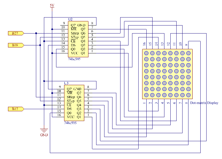
In this experiment, a CA dot matrix is used. You can see the label ends with “BS”. The wiring and code are done for the CA matrix. Therefore, if you happen to have a CC matrix, you need to change the wiring and code. In addition, two 74HC595 chips are used here. One is to control the rows of the dot matrix while the other, the columns.
The Schematic Diagram
Experimental Procedures
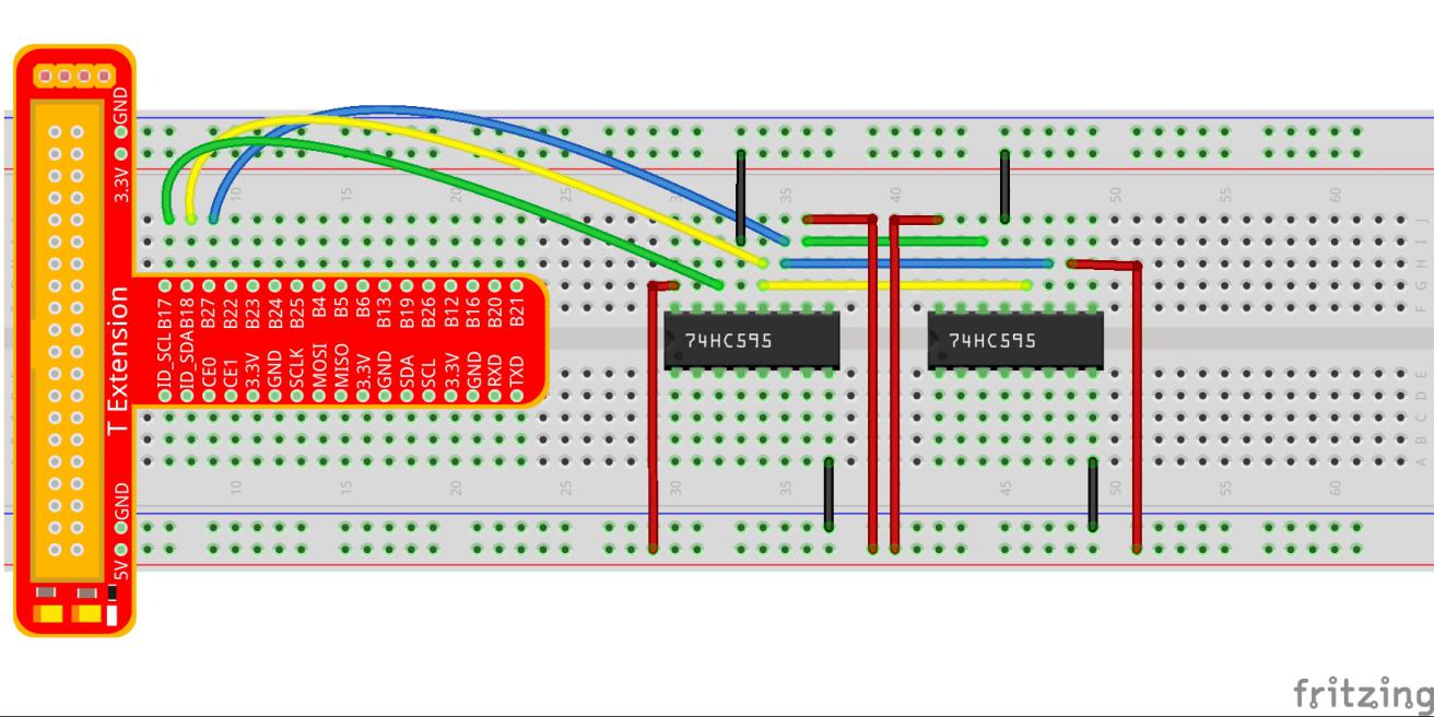
Step 1: Build the circuit. Since the wiring is complicated, let’s make it step by step. First, inset the T-Cobbler and two 74HC595 chips into breadboard. Connect the 5V and GND of the T-Cobbler to holes on the two sides of the board, then hook up pin16 and 10 of the two 74HC595 chips to VCC and pin 13 respectively, and pin 8 to GND.
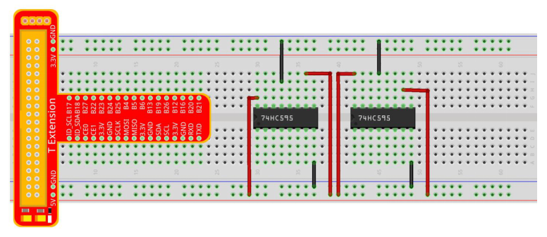
Step 2: Connect pin 11 of the two 74HC595 together, and then to GPIO27; then pin 12 of the two chips, and to GPIO18; next, pin 14 of the 74HC595 on the left side to GPIO17 and pin 9 to pin 14 of the other 74HC595.
Step 3: Insert the dot matrix onto the breadboard. The 74HC595 on the right side is to control columns of the matrix. See the table below for the mapping. Therefore, Q0-Q7 pins of the 74HC595 are mapped with pin 13, 3, 4, 10, 6, 11, 15, and 16 respectively.
COL |
1 |
2 |
3 |
4 |
5 |
6 |
7 |
8 |
Pin No. |
13 |
3 |
4 |
10 |
6 |
11 |
15 |
16 |
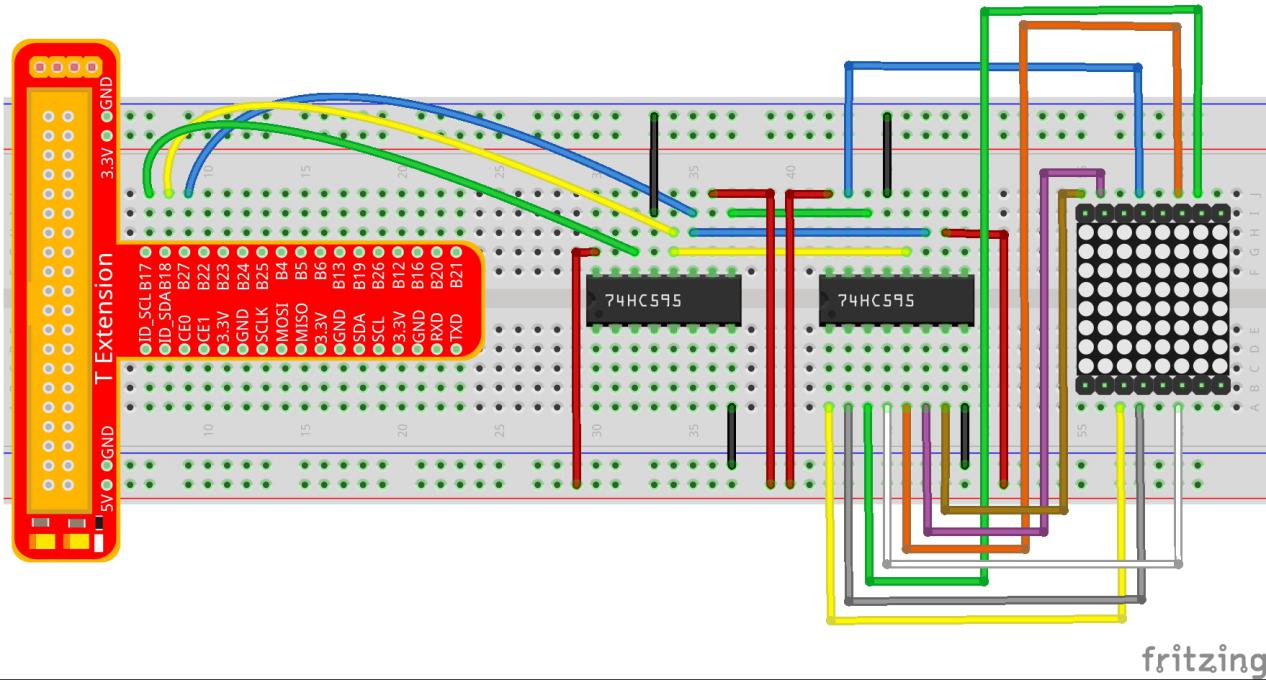
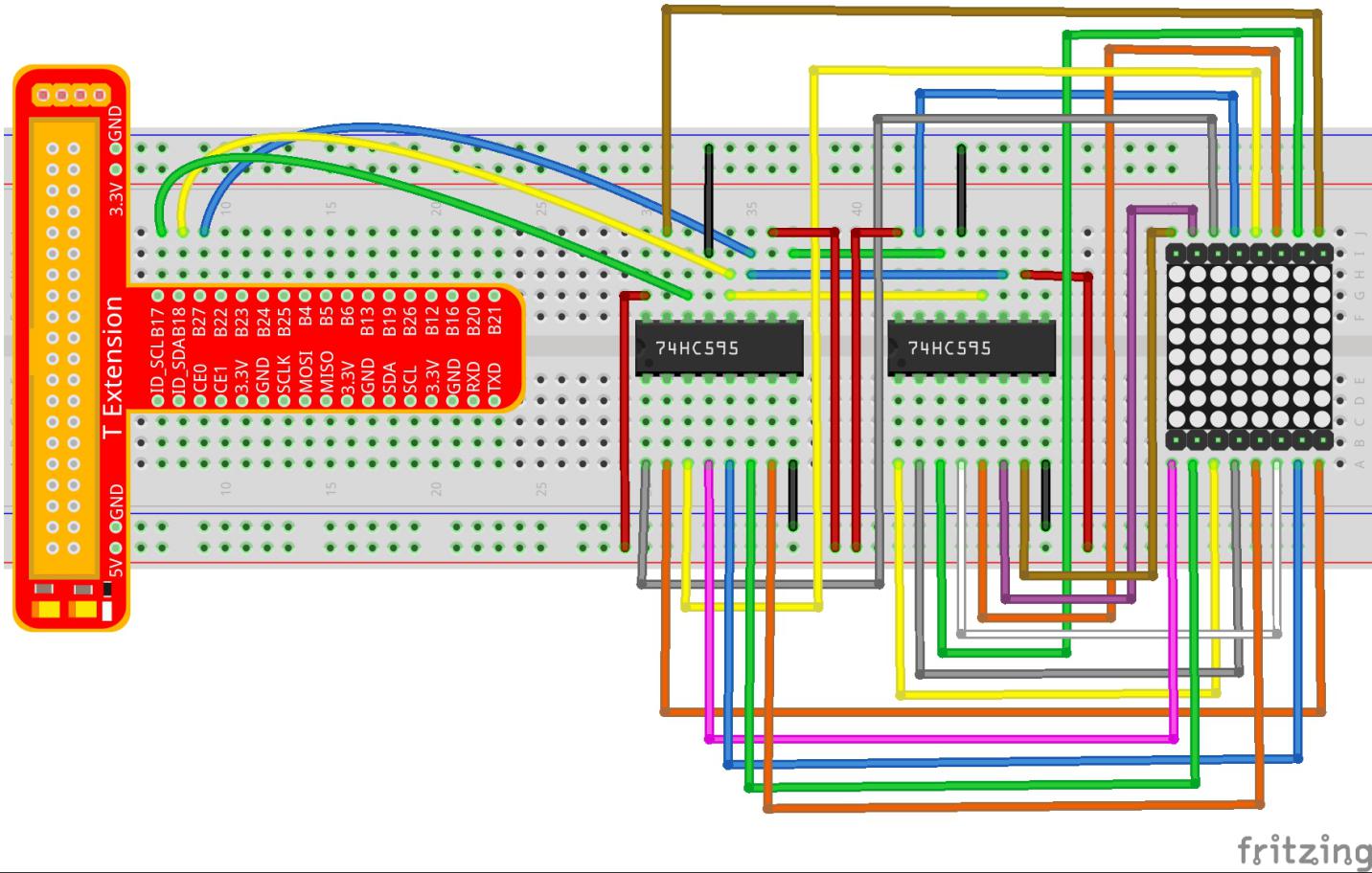
Step 4: Now connect the ROWs of the dot matrix. The 74HC595 on the left controls ROW of the matrix. See the table below for the mapping. We can see, Q0-Q7 of the 74HC595 on the left are mapped with pin 9, 14, 8, 12, 1, 7, 2, and 5 respectively.
ROW |
1 |
2 |
3 |
4 |
5 |
6 |
7 |
8 |
Pin No. |
9 |
14 |
8 |
12 |
1 |
7 |
2 |
5 |
Note
PLEASE connect devices correctly. DO NOT wire up insufficiently. DO NOT connect to the wrong side of the dot matrix. In the Fritzing image above, the side with label is at the bottom.
For C Language Users:
Step 2: Get into the folder of code.
cd /home/pi/SunFounder_Super_Kit_V3.0_for_Raspberry_Pi/C
Step 3: Compile.
make 15_dotMatrix
Step 4: Run.
sudo ./15_dotMatrix
Note
If it does not work after running, or there is an error prompt: “wiringPi.h: No such file or directory”, please refer to C code is not working?.
Code
#include <wiringPi.h>
#include <stdio.h>

#define   SDI   0   //serial data input
#define   RCLK  1   //memory clock input(STCP)
#define   SRCLK 2   //shift register clock input(SHCP)

unsigned char code_H[20] = {0x01,0xff,0x80,0xff,0x01,0x02,0x04,0x08,0x10,0x20,0x40,0x80,0xff,0xff,0xff,0xff,0xff,0xff,0xff,0xff};
unsigned char code_L[20] = {0x00,0x7f,0x00,0xfe,0x00,0x00,0x00,0x00,0x00,0x00,0x00,0x00,0xfe,0xfd,0xfb,0xf7,0xef,0xdf,0xbf,0x7f};

//unsigned char code_L[8] = {0x00,0x00,0x3c,0x42,0x42,0x3c,0x00,0x00};
//unsigned char code_H[8] = {0xff,0xe7,0xdb,0xdb,0xdb,0xdb,0xe7,0xff};

//unsigned char code_L[8] = {0xff,0xff,0xc3,0xbd,0xbd,0xc3,0xff,0xff};
//unsigned char code_H[8] = {0x00,0x18,0x24,0x24,0x24,0x24,0x18,0x00};

void init(void){
    pinMode(SDI, OUTPUT); //make P0 output
    pinMode(RCLK, OUTPUT); //make P0 output
    pinMode(SRCLK, OUTPUT); //make P0 output

    digitalWrite(SDI, 0);
    digitalWrite(RCLK, 0);
    digitalWrite(SRCLK, 0);
}

void hc595_in(unsigned char dat){
    int i;

    for(i=0;i<8;i++){
        digitalWrite(SDI, 0x80 & (dat << i));
        digitalWrite(SRCLK, 1);
        delay(1);
        digitalWrite(SRCLK, 0);
    }
}

void hc595_out(){
    digitalWrite(RCLK, 1);
    delay(1);
    digitalWrite(RCLK, 0);
}

int main(void){
    int i;

    if(wiringPiSetup() == -1){ //when initialize wiring failed, print messageto screen
        printf("setup wiringPi failed !");
        return 1;
    }

    init();

    printf("\n");
    printf("\n");
    printf("========================================\n");
    printf("|      Dot matrix with two 74HC595     |\n");
    printf("|    ------------------------------    |\n");
    printf("|         SDI connect to GPIO0         |\n");
    printf("|         RCLK connect to GPIO1        |\n");
    printf("|        SRCLK connect to GPIO 2       |\n");
    printf("|                                      |\n");
    printf("|    Control Dot matrix with 74HC595   |\n");
    printf("|                                      |\n");
    printf("|                            SunFounder|\n");
    printf("========================================\n");
    printf("\n");
    printf("\n");

    while(1){
        for(i=0;i<sizeof(code_H);i++){
            hc595_in(code_L[i]);
            hc595_in(code_H[i]);
            hc595_out();
            delay(100);
        }

        for(i=sizeof(code_H);i>=0;i--){
            hc595_in(code_L[i]);
            hc595_in(code_H[i]);
            hc595_out();
            delay(100);
        }
    }

    return 0;
}
Code Explanation
void hc595_in(unsigned char dat)
{
    // Write an 8-bit data to the shift register of the 74HC595

    int i;

    for(i=0;i<8;i++)
    {

        digitalWrite(SDI, 0x80 & (dat << i));
        // Write the value of dat to pin SDI of the HC595 bit by bit

        digitalWrite(SRCLK, 1); // Everytime SRCLK adds one, the shift register moves 1 bit

        delay(1);

        digitalWrite(SRCLK, 0);

    }

}

void hc595_out()
{ // Update the output data of the 74HC596

    digitalWrite(RCLK, 1); // Everytime RCLK adds 1, the HC595 updates the output.

    delay(1);

    digitalWrite(RCLK, 0);

}


while(1)
{

    for(i=0;i<sizeof(code_H);i++){
        // The data of ROW and COL table for the matrix adds 1 each time.

        hc595_in(code_L[i]); // Write to the first data of the Row table

        hc595_in(code_H[i]);
        // Write to the first data of the COL table, and the ROW data previously goes to the other HC595.

        hc595_out(); /* Update the output of the 74HC595; output the data
        controlled by both two HC595, and the dot matrix will show the pattern. */

        delay(100);

    }

    for(i=sizeof(code_H);i>=0;i--)
    { // The data of ROW and COL table for the matrix decreases by 1 each time.

        hc595_in(code_L[i]); // Write to the first data of the Row table

        hc595_in(code_H[i]); /* Write to the first data of the COL table, and
        the ROW data previously goes to the other HC595. */

        hc595_out(); /* Update the output of the 74HC595; output the data
        controlled by both two HC595, and the dot matrix will show the pattern. */

        delay(100);

    }

}
For Python Users:
Step 2: Get into the folder of code.
cd /home/pi/SunFounder_Super_Kit_V3.0_for_Raspberry_Pi/Python
Step 3: Run.
sudo python3 15_dotMatrix.py
Code
import RPi.GPIO as GPIO
import time
from sys import version_info

if version_info.major == 3:
    raw_input = input

SDI   = 17
RCLK  = 18
SRCLK = 27

# we use BX matrix, ROW for anode, and COL for cathode
# ROW  ++++
code_H = [0x01,0xff,0x80,0xff,0x01,0x02,0x04,0x08,0x10,0x20,0x40,0x80,0xff,0xff,0xff,0xff,0xff,0xff,0xff,0xff]
# COL  ----
code_L = [0x00,0x7f,0x00,0xfe,0x00,0x00,0x00,0x00,0x00,0x00,0x00,0x00,0xfe,0xfd,0xfb,0xf7,0xef,0xdf,0xbf,0x7f]

def print_msg():
    print ("========================================")
    print ("|      Dot matrix with two 74HC595     |")
    print ("|    ------------------------------    |")
    print ("|        SDI connect to GPIO17         |")
    print ("|        RCLK connect to GPIO18        |")
    print ("|        SRCLK connect to GPIO27       |")
    print ("|                                      |")
    print ("|   Control Dot matrix with 74HC595    |")
    print ("|                                      |")
    print ("|                            SunFounder|")
    print ("========================================")
    print ("Program is running...")
    print ("Please press Ctrl+C to end the program...")
    #raw_input ("Press Enter to begin\n")

def print_matrix(matrix):
    for i in range(0,len(matrix)):
        print (matrix[i])

def get_matrix(row_buffer, col_buffer, max_row=8, max_col=8):
    matrix_msg = [[0 for i in range(max_row)] for i in range(max_col)]

    print("row_buffer = 0x%02x , col_buffer = 0x%02x"%(row_buffer, col_buffer))
    for row_num in range(0,8):
        for col_num in range(0,8):
            #print (row_num, col_num), '-->', (((row_buffer >> row_num) & 0x01), ((col_buffer >> col_num) & 0x01))
            if (((row_buffer >> row_num) & 0x01) - ((col_buffer >> col_num) & 0x01)):
                matrix_msg[row_num][col_num] = 1
    print_matrix(matrix_msg)
    matrix_msg = [[0 for i in range(max_row)] for i in range(max_col)]

def setup():
    GPIO.setmode(GPIO.BCM)    # Number GPIOs by its BCM location
    GPIO.setup(SDI, GPIO.OUT)
    GPIO.setup(RCLK, GPIO.OUT)
    GPIO.setup(SRCLK, GPIO.OUT)
    GPIO.output(SDI, GPIO.LOW)
    GPIO.output(RCLK, GPIO.LOW)
    GPIO.output(SRCLK, GPIO.LOW)

# Shift the data to 74HC595
def hc595_shift(dat):
    for bit in range(0, 8):
        GPIO.output(SDI, 0x80 & (dat << bit))
        GPIO.output(SRCLK, GPIO.HIGH)
        time.sleep(0.001)
        GPIO.output(SRCLK, GPIO.LOW)
    GPIO.output(RCLK, GPIO.HIGH)
    time.sleep(0.001)
    GPIO.output(RCLK, GPIO.LOW)

def main():
    print_msg()
    while True:
        for i in range(0, len(code_H)):
            hc595_shift(code_L[i])
            hc595_shift(code_H[i])
            get_matrix(code_L[i], code_H[i])
            time.sleep(0.1)

        for i in range(len(code_H)-1, -1, -1):
            hc595_shift(code_L[i])
            hc595_shift(code_H[i])
            get_matrix(code_L[i], code_H[i])
            time.sleep(0.1)

def destroy():
    GPIO.cleanup()

if __name__ == '__main__':
    setup()
    try:
        main()
    except KeyboardInterrupt:
        destroy()
Code Explanation
# We use a Common Anode matrix, so ROW pins are the common anode, and COL, the common cathode.

''' row and column lists. When characters are displayed, an element in row
and one in column are acquired and assigned to the two HC595 chips
respectively. Thus a pattern is shown on the matrix. '''

# ROW ++++

code_H = [0x01,0xff,0x80,0xff,0x01,0x02,0x04,0x08,0x10,0x20,0x40,0x80,
          0xff,0xff,0xff,0xff,0xff,0xff,0xff,0xff]

# COL ----

code_L = [0x00,0x7f,0x00,0xfe,0x00,0x00,0x00,0x00,0x00,0x00,0x00,0x00,0xfe,
          0xfd,0xfb,0xf7,0xef,0xdf,0xbf,0x7f]

def get_matrix(row_buffer, col_buffer, max_row=8, max_col=8):
# The functions is to print the pattern on the matrix by the 2D array on the command line interface (CLI).

    matrix_msg = [[0 for i in range(max_row)] for i in range(max_col)] # Initialize a 2D array

    print ("row_buffer = 0x%02x , col_buffer = 0x%02x"%(row_buffer, col_buffer))

    for row_num in range(0,8):

        for col_num in range(0,8):

            if (((row_buffer >> row_num) & 0x01) - ((col_buffer >> col_num) & 0x01)):
            # for Common Anode type matrix, when row is High and column is low, the LED will light up.

                matrix_msg[row_num][col_num] = 1 ''' To turn on an LED at a certain row
                and column, assign 1 to the corresponding elements in the 2D array'''

    print_matrix(matrix_msg) # Print the 2D array on the CLI

    matrix_msg = [[0 for i in range(max_row)] for i in range(max_col)]
    # Reset the array after one print

def hc595_shift(dat): # Shift the data to 74HC595

    for bit in range(0, 8):

        GPIO.output(SDI, 0x80 & (dat << bit)) # Write the value of dat bit by bit to pin SDI of the HC595

        GPIO.output(SRCLK, GPIO.HIGH) # Everytime SRCLK is High, the shift register shifts one bit

        time.sleep(0.001)

        GPIO.output(SRCLK, GPIO.LOW)

    GPIO.output(RCLK, GPIO.HIGH) # Everytime RCLK is high, HC595 updates its output.

    time.sleep(0.001)

    GPIO.output(RCLK, GPIO.LOW)

def main():

    print_msg()

    while True:

        for i in range(0, len(code_H)): # Assign elements of the column table in sequence

            hc595_shift(code_L[i]) # Write to the first data of the Row table

            hc595_shift(code_H[i])
            # Write to the first data of the COL table, and the ROW data previously goes to the other HC595.

            get_matrix(code_L[i], code_H[i]) # Print the 2D array on the CLI

            time.sleep(0.1)

        for i in range(len(code_H)-1, -1, -1): # Assign elements of the column table in inverse order

            hc595_shift(code_L[i])

            hc595_shift(code_H[i])

            get_matrix(code_L[i], code_H[i])

            time.sleep(0.1)
You should see LEDs light up as you control.
Summary
Through this lesson, you have got the basic principle of LED dot matrix and how to program the Raspberry Pi to drive an LED dot matrix based on 74HC595 cascade. With the knowledge learnt, try more fascinating creations!
Further Exploration
If you want to display characters on the matrix, please refer to a python code: https://github.com/sunfounder/SunFounder_Dot_Matrix.