Note
Hello, welcome to the SunFounder Raspberry Pi & Arduino & ESP32 Enthusiasts Community on Facebook! Dive deeper into Raspberry Pi, Arduino, and ESP32 with fellow enthusiasts.
Why Join?
Expert Support: Solve post-sale issues and technical challenges with help from our community and team.
Learn & Share: Exchange tips and tutorials to enhance your skills.
Exclusive Previews: Get early access to new product announcements and sneak peeks.
Special Discounts: Enjoy exclusive discounts on our newest products.
Festive Promotions and Giveaways: Take part in giveaways and holiday promotions.
👉 Ready to explore and create with us? Click [here] and join today!
4.1.8 Battery Indicator
Note

Depending on your kit version, please identify whether you have ADC0834 or MCP3008 and proceed with the matching section.
Introduction
In this project, we will make a battery indicator device that can visually display the battery level on the LED Bargraph.
Warning
Do not use battery components that exceed 3.3V to avoid overloading, which may damage the chip or Raspberry Pi.
Required Components
In this project, we need the following components.
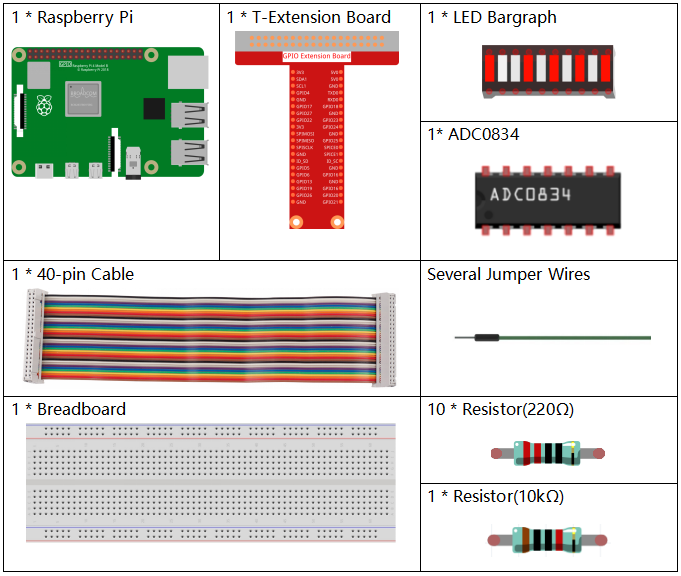
It’s definitely convenient to buy a whole kit, here’s the link:
Name |
ITEMS IN THIS KIT |
LINK |
|---|---|---|
Raphael Kit |
337 |
You can also buy them separately from the links below.
COMPONENT INTRODUCTION |
PURCHASE LINK |
|---|---|
- |
|
- |
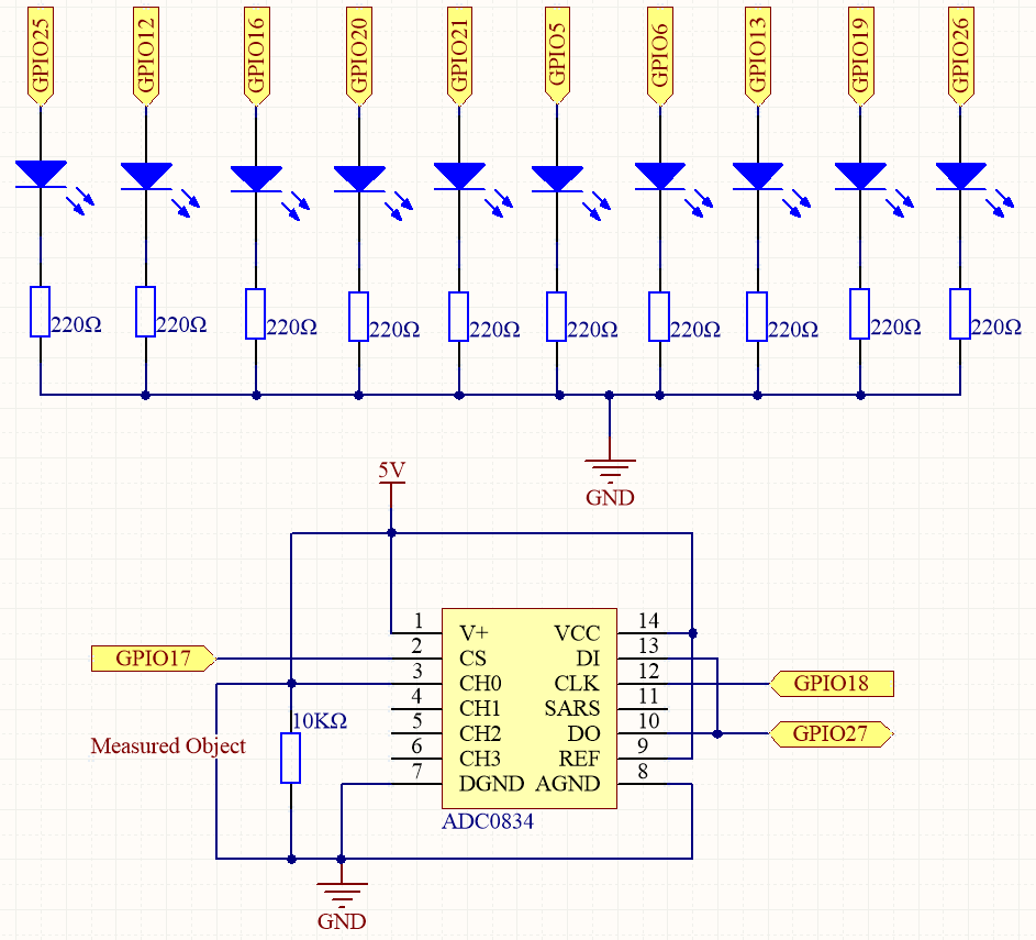
Schematic Diagram
T-Board Name |
physical |
wiringPi |
BCM |
GPIO17 |
Pin 11 |
0 |
17 |
GPIO18 |
Pin 12 |
1 |
18 |
GPIO27 |
Pin 13 |
2 |
27 |
GPIO25 |
Pin 22 |
6 |
25 |
GPIO12 |
Pin 32 |
26 |
12 |
GPIO16 |
Pin 36 |
27 |
16 |
GPIO20 |
Pin 38 |
28 |
20 |
GPIO21 |
Pin 40 |
29 |
21 |
GPIO5 |
Pin 29 |
21 |
5 |
GPIO6 |
Pin 31 |
22 |
6 |
GPIO13 |
Pin 33 |
23 |
13 |
GPIO19 |
Pin 35 |
24 |
19 |
GPIO26 |
Pin 37 |
25 |
26 |
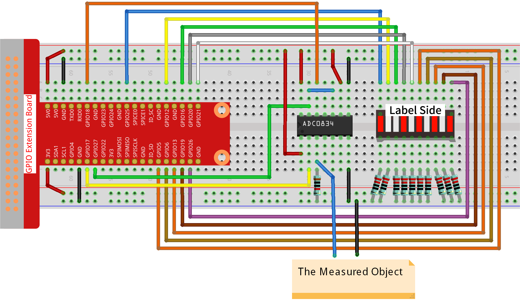
Experimental Procedures
Step 1: Build the circuit.
Step 2: Go to the folder of the code.
cd ~/raphael-kit/python-pi5
Step 3: Run the executable file.
sudo python3 4.1.11_BatteryIndicator_zero.py
After the program runs, give the 3rd pin of ADC0834 and the GND a lead-out wire separately and then lead them to the two poles of a battery separately. You can see the corresponding LED on the LED Bargraph is lit up to display the power level (measuring range: 0-5V).
Warning
If there is an error prompt RuntimeError: Cannot determine SOC peripheral base address, please refer to If gpiozero doesn’t work.
Code
Note
You can Modify/Reset/Copy/Run/Stop the code below. But before that, you need to go to source code path like raphael-kit/python-pi5. After modifying the code, you can run it directly to see the effect.
#!/usr/bin/env python3
from gpiozero import LED
import spidev
import time

# List of GPIO pins to which LEDs are connected
ledPins = [25, 12, 16, 20, 21, 5, 6, 13, 19, 26]
# Initialize LED objects for each pin in the list
leds = [LED(pin) for pin in ledPins]

# Setup SPI for MCP3008
spi = spidev.SpiDev()
spi.open(0, 0)              # Open SPI bus 0, device (CE0)
spi.max_speed_hz = 1000000  # Set SPI speed to 1 MHz

def read_adc(channel=0):
    """
    Reads analog value from MCP3008 channel (default CH0).
    Returns a 10-bit value .
    """
    if channel < 0 or channel > 7:
        return -1
    r = spi.xfer2([1, (8 + channel) << 4, 0])
    value = ((r[1] & 0x03) << 8) | r[2]
    return value

def LedBarGraph(value):
    # Turn off all LEDs
    for i in range(10):
        leds[i].on()
    # Turn on LEDs up to the specified value
    for i in range(min(value, 10)):
        leds[i].off()

try:
    # Main loop to continuously update LED bar graph
    while True:
        analogVal = read_adc(0)  # Read from CH0
        LedBarGraph(int(analogVal / 102.4))
        time.sleep(0.1)
except KeyboardInterrupt:
    # Turn off all LEDs when program is interrupted
    for i in range(10):
        leds[i].off()
    spi.close()
Code Explanation
This section imports the necessary libraries. gpiozero is used for controlling GPIO pins (specifically LEDs), spidev is used to interface with the MCP3008 ADC over SPI, and time is used for delays.
#!/usr/bin/env python3
from gpiozero import LED
import spidev
import time
Defines the GPIO pins to which the LEDs are connected and creates a list of LED objects. These are used to represent a bar graph.
# List of GPIO pins to which LEDs are connected
ledPins = [25, 12, 16, 20, 21, 5, 6, 13, 19, 26]
# Initialize LED objects for each pin in the list
leds = [LED(pin) for pin in ledPins]
Initializes SPI communication for the MCP3008 ADC on SPI bus 0 using CE0. The speed is set to 1 MHz.
# Setup SPI for MCP3008
spi = spidev.SpiDev()
spi.open(0, 0)              # Open SPI bus 0, device (CE0)
spi.max_speed_hz = 1000000  # Set SPI speed to 1 MHz
Reads a 10-bit analog value (0–1023) from the specified MCP3008 channel. Channel 0 is used by default.
def read_adc(channel=0):
    """
    Reads analog value from MCP3008 channel (default CH0).
    Returns a 10-bit value .
    """
    if channel < 0 or channel > 7:
        return -1
    r = spi.xfer2([1, (8 + channel) << 4, 0])
    value = ((r[1] & 0x03) << 8) | r[2]
    return value
This function turns on all LEDs first (reset state), then turns off a number of LEDs based on the scaled input value. It creates a reverse bar graph effect (more value = fewer LEDs lit).
def LedBarGraph(value):
    # Turn off all LEDs
    for i in range(10):
        leds[i].on()
    # Turn on LEDs up to the specified value
    for i in range(min(value, 10)):
        leds[i].off()
Continuously reads the analog value from MCP3008 CH0 and updates the LED bar graph. The analog value is divided by 102.4 to scale it from 0–1023 to a 0–10 LED level.
try:
    # Main loop to continuously update LED bar graph
    while True:
        analogVal = read_adc(0)  # Read from CH0
        LedBarGraph(int(analogVal / 102.4))
        time.sleep(0.1)
Ensures all LEDs are turned off and SPI is closed when the program is interrupted (e.g., by pressing Ctrl+C).
except KeyboardInterrupt:
    # Turn off all LEDs when program is interrupted
    for i in range(10):
        leds[i].off()
    spi.close()