Note
Hello, welcome to the SunFounder Raspberry Pi & Arduino & ESP32 Enthusiasts Community on Facebook! Dive deeper into Raspberry Pi, Arduino, and ESP32 with fellow enthusiasts.
Why Join?
Expert Support: Solve post-sale issues and technical challenges with help from our community and team.
Learn & Share: Exchange tips and tutorials to enhance your skills.
Exclusive Previews: Get early access to new product announcements and sneak peeks.
Special Discounts: Enjoy exclusive discounts on our newest products.
Festive Promotions and Giveaways: Take part in giveaways and holiday promotions.
👉 Ready to explore and create with us? Click [here] and join today!
4.1.8 Battery Indicator(MCP3008)
Note

Depending on your kit version, please identify whether you have ADC0834 or MCP3008 and proceed with the matching section.
Introduction
In this project, we will make a battery indicator device that can visually display the battery level on the LED Bargraph.
Warning
Do not use battery components that exceed 3.3V to avoid overloading, which may damage the chip or Raspberry Pi.
Required Components
In this project, we need the following components.
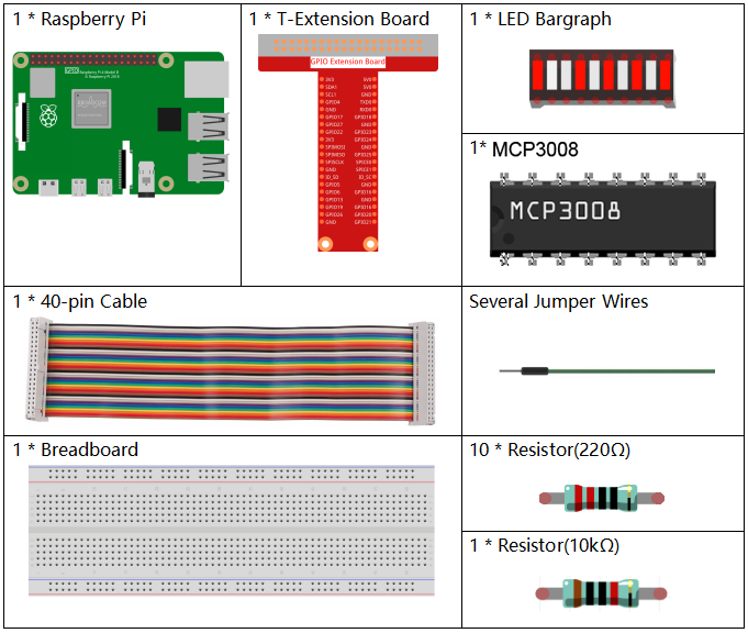
It’s definitely convenient to buy a whole kit, here’s the link:
Name |
ITEMS IN THIS KIT |
LINK |
|---|---|---|
Raphael Kit |
337 |
You can also buy them separately from the links below.
COMPONENT INTRODUCTION |
PURCHASE LINK |
|---|---|
- |
|
- |
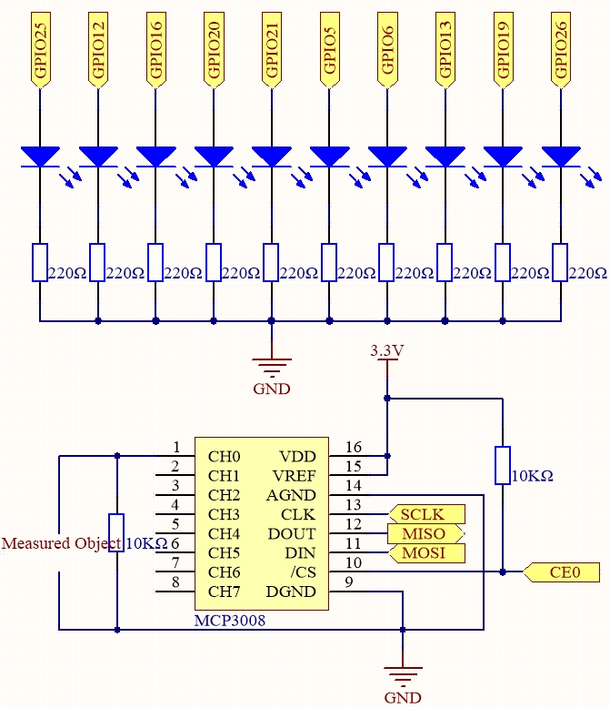
Schematic Diagram
T-Board Name |
physical |
wiringPi |
BCM |
SPICE0 |
Pin 24 |
10 |
8 |
SPIMOSI |
Pin 19 |
12 |
10 |
SPIMISO |
Pin 21 |
13 |
9 |
SPISCLK |
Pin 23 |
14 |
11 |
GPIO25 |
Pin 22 |
6 |
25 |
GPIO12 |
Pin 32 |
26 |
12 |
GPIO16 |
Pin 36 |
27 |
16 |
GPIO20 |
Pin 38 |
28 |
20 |
GPIO21 |
Pin 40 |
29 |
21 |
GPIO5 |
Pin 29 |
21 |
5 |
GPIO6 |
Pin 31 |
22 |
6 |
GPIO13 |
Pin 33 |
23 |
13 |
GPIO19 |
Pin 35 |
24 |
19 |
GPIO26 |
Pin 37 |
25 |
26 |
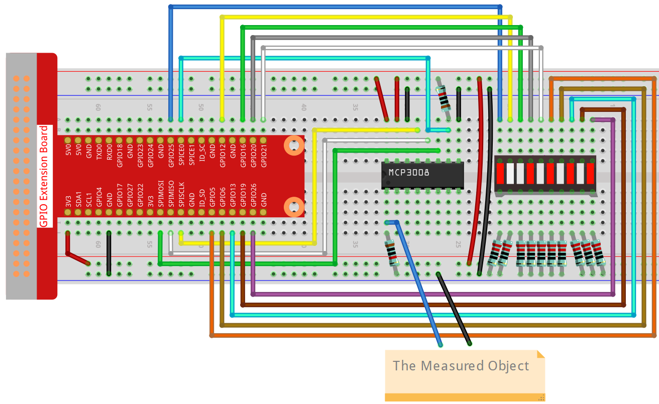
Experimental Procedures
Step 1: Build the circuit.
Step 2: Set up the SPI interface and install the spidev library (see SPI Configuration for detailed instructions). If you have already completed these steps, you can skip this.
Step 3: Go to the folder of the code.
cd ~/raphael-kit/python-pi5
Step 4: Run the executable file.
sudo python3 4.1.11-2_Battery_indicator_zero.py
After the program runs, give the 3rd pin of MCP3008 and the GND a lead-out wire separately and then lead them to the two poles of a battery separately. You can see the corresponding LED on the LED Bargraph is lit up to display the power level (measuring range: 0-5V).
Warning
If there is an error prompt RuntimeError: Cannot determine SOC peripheral base address, please refer to If gpiozero doesn’t work.
Code
Note
You can Modify/Reset/Copy/Run/Stop the code below. But before that, you need to go to source code path like raphael-kit/python-pi5. After modifying the code, you can run it directly to see the effect.
#!/usr/bin/env python3

import LCD1602
from gpiozero import LED, Buzzer, Button
import spidev
import time
import math

# Initialize joystick button, buzzer, and LED
Joy_BtnPin = Button(22)  # GPIO22, Pin15
buzzPin = Buzzer(23)     # GPIO23, Pin16
ledPin = LED(24)         # GPIO24, Pin18

# Set initial upper temperature threshold
upperTem = 40

# Initialize SPI for MCP3008 (Bus 0, CE0 -> GPIO8 / Pin24)
spi = spidev.SpiDev()
spi.open(0, 0)
spi.max_speed_hz = 1000000  # 1 MHz

# Initialize LCD (I2C address 0x27, backlight on)
LCD1602.init(0x27, 1)

def read_adc(channel):
    """
    Read analog value from MCP3008
    """
    if channel < 0 or channel > 7:
        return -1
    adc = spi.xfer2([1, (8 + channel) << 4, 0])
    value = ((adc[1] & 0x03) << 8) | adc[2]
    return value

def get_joystick_value():
    """
    Reads the joystick values and returns a change value based on the joystick's position.
    """
    x_val = read_adc(1)
    y_val = read_adc(2)
    if x_val > 800:
        return 1
    elif x_val < 200:
        return -1
    elif y_val > 800:
        return -10
    elif y_val < 200:
        return 10
    else:
        return 0

def upper_tem_setting():
    """
    Adjusts and displays the upper temperature threshold on the LCD.
    """
    global upperTem
    LCD1602.write(0, 0, 'Upper Adjust: ')
    change = int(get_joystick_value())
    upperTem += change
    strUpperTem = str(upperTem)
    LCD1602.write(0, 1, strUpperTem)
    LCD1602.write(len(strUpperTem), 1, '              ')
    time.sleep(0.1)

def temperature():
    """
    Reads the current temperature from the sensor and returns it in Celsius.
    """
    analogVal = read_adc(0)
    Vr = 3.3 * analogVal / 1023.0  # Voltage across the fixed resistor
    if Vr == 0:
        return 0  # Prevent division by zero
    Rt = 10000.0 * (3.3 - Vr) / Vr  # Adjusted formula: thermistor voltage is (3.3 - Vr)
    temp = 1 / (((math.log(Rt / 10000.0)) / 3950.0) + (1 / (273.15 + 25.0)))
    Cel = temp - 273.15
    return round(Cel, 2)

def monitoring_temp():
    """
    Monitors and displays the current temperature and upper temperature threshold.
    Activates buzzer and LED if the temperature exceeds the upper limit.
    """
    global upperTem
    Cel = temperature()
    LCD1602.write(0, 0, 'Temp: ')
    LCD1602.write(0, 1, 'Upper: ')
    LCD1602.write(6, 0, str(Cel))
    LCD1602.write(7, 1, str(upperTem))
    time.sleep(0.1)
    if Cel >= upperTem:
        buzzPin.on()
        ledPin.on()
    else:
        buzzPin.off()
        ledPin.off()

# Main execution loop
try:
    lastState = 1
    stage = 0
    while True:
        currentState = Joy_BtnPin.value
        if currentState == 1 and lastState == 0:
            stage = (stage + 1) % 2
            time.sleep(0.1)
            LCD1602.clear()
        lastState = currentState
        if stage == 1:
            upper_tem_setting()
        else:
            monitoring_temp()
except KeyboardInterrupt:
    LCD1602.clear()
    spi.close()
Code Explanation
This Python program runs on a Raspberry Pi. It uses an MCP3008 analog-to-digital converter to read temperature data from an analog sensor. A joystick is used to adjust the temperature threshold, and an LCD1602 display shows the current temperature and threshold. A buzzer and LED are triggered when the temperature exceeds the threshold.
Import Required Libraries
#!/usr/bin/env python3

import RPi.GPIO as GPIO
import spidev
import time
import math
import LCD1602
RPi.GPIOis used for controlling GPIO pins.spidevcommunicates with MCP3008 using SPI.mathis needed for temperature conversion calculations.LCD1602controls the LCD display.
GPIO Setup
JOY_BTN_PIN = 22
BUZZER_PIN = 23
LED_PIN = 24

GPIO.setmode(GPIO.BCM)
GPIO.setup(JOY_BTN_PIN, GPIO.IN, pull_up_down=GPIO.PUD_UP)
GPIO.setup(BUZZER_PIN, GPIO.OUT)
GPIO.setup(LED_PIN, GPIO.OUT)
Assigns pins for joystick button, buzzer, and LED using BCM numbering.
Configures the joystick button with a pull-up resistor and sets output pins LOW initially.
SPI and LCD Initialization
upperTem = 40  # Default temperature threshold

spi = spidev.SpiDev()
spi.open(0, 0)
spi.max_speed_hz = 1000000  # 1 MHz

LCD1602.init(0x27, 1)
Initializes SPI communication for the MCP3008.
Sets up the I2C LCD1602 at address
0x27.
Read ADC Channel
def read_adc(channel):
    if channel < 0 or channel > 7:
        return -1
    adc = spi.xfer2([1, (8 + channel) << 4, 0])
    value = ((adc[1] & 0x03) << 8) | adc[2]
    return value
Sends SPI commands to MCP3008 to read analog voltage from the selected channel (0–7).
Returns a 10-bit result between 0 and 1023.
Joystick Direction Input
def get_joystick_value():
    x_val = read_adc(1)
    y_val = read_adc(2)
    if x_val > 800:
        return 1
    elif x_val < 200:
        return -1
    elif y_val > 800:
        return -10
    elif y_val < 200:
        return 10
    else:
        return 0
Reads horizontal (X) and vertical (Y) joystick movement and translates that into a change in threshold:
Up/Down adjusts by 10.
Left/Right adjusts by 1.
Adjust Temperature Threshold
def upper_tem_setting():
    global upperTem
    LCD1602.write(0, 0, 'Upper Adjust: ')
    change = int(get_joystick_value())
    upperTem += change
    strUpperTem = str(upperTem)
    LCD1602.write(0, 1, strUpperTem)
    LCD1602.write(len(strUpperTem), 1, '              ')
    time.sleep(0.1)
Allows the user to change the
upperTemthreshold via joystick.Updates LCD to display the current threshold value.
Calculate Temperature from Analog Sensor
def temperature():
    analogVal = read_adc(0)
    Vr = 3.3 * analogVal / 1023.0
    if Vr == 0:
        return 0
    Rt = 10000.0 * (3.3 - Vr) / Vr
    tempK = 1.0 / (((math.log(Rt / 10000.0)) / 3950.0) + (1.0 / (273.15 + 25.0)))
    Cel = tempK - 273.15
    return round(Cel, 2)
Converts voltage reading to resistance, then uses the Steinhart-Hart equation to compute the temperature in Celsius.
Monitoring Mode
def monitoring_temp():
    global upperTem
    Cel = temperature()
    LCD1602.write(0, 0, 'Temp: ')
    LCD1602.write(0, 1, 'Upper: ')
    LCD1602.write(6, 0, str(Cel))
    LCD1602.write(7, 1, str(upperTem))
    time.sleep(0.1)
    if Cel >= upperTem:
        GPIO.output(BUZZER_PIN, GPIO.HIGH)
        GPIO.output(LED_PIN, GPIO.HIGH)
    else:
        GPIO.output(BUZZER_PIN, GPIO.LOW)
        GPIO.output(LED_PIN, GPIO.LOW)
Displays the current temperature and threshold.
Activates buzzer and LED if the current temperature exceeds the threshold.
Main Loop
try:
    lastState = GPIO.input(JOY_BTN_PIN)
    stage = 0
    while True:
        currentState = GPIO.input(JOY_BTN_PIN)
        if currentState == GPIO.HIGH and lastState == GPIO.LOW:
            stage = (stage + 1) % 2
            time.sleep(0.1)
            LCD1602.clear()
        lastState = currentState

        if stage == 1:
            upper_tem_setting()
        else:
            monitoring_temp()
Uses joystick button press to toggle between:
stage 0: temperature monitoringstage 1: threshold adjustment
Cleanup on Exit
except KeyboardInterrupt:
    pass

finally:
    LCD1602.clear()
    GPIO.cleanup()
    spi.close()
Ensures GPIO and LCD are reset on program termination (e.g., Ctrl+C).