Note
Hello, welcome to the SunFounder Raspberry Pi & Arduino & ESP32 Enthusiasts Community on Facebook! Dive deeper into Raspberry Pi, Arduino, and ESP32 with fellow enthusiasts.
Why Join?
Expert Support: Solve post-sale issues and technical challenges with help from our community and team.
Learn & Share: Exchange tips and tutorials to enhance your skills.
Exclusive Previews: Get early access to new product announcements and sneak peeks.
Special Discounts: Enjoy exclusive discounts on our newest products.
Festive Promotions and Giveaways: Take part in giveaways and holiday promotions.
👉 Ready to explore and create with us? Click [here] and join today!
1.1.3 LED Bar Graph
Introduction
In this project, we sequentially illuminate the lights on the LED Bar Graph.
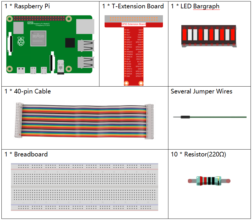
Required Components
In this project, we need the following components.
Name |
ITEMS IN THIS KIT |
LINK |
|---|---|---|
Raphael Kit |
337 |
You can also buy them separately from the links below.
COMPONENT INTRODUCTION |
PURCHASE LINK |
|---|---|
- |
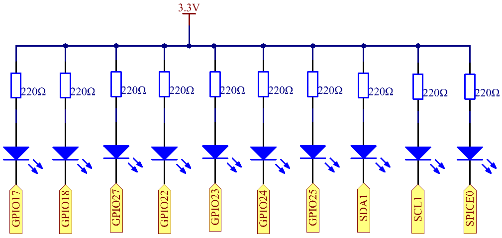
Schematic Diagram
T-Board Name |
physical |
wiringPi |
BCM |
GPIO17 |
Pin 11 |
0 |
17 |
GPIO18 |
Pin 12 |
1 |
18 |
GPIO27 |
Pin 13 |
2 |
27 |
GPIO22 |
Pin 15 |
3 |
22 |
GPIO23 |
Pin 16 |
4 |
23 |
GPIO24 |
Pin 18 |
5 |
24 |
GPIO25 |
Pin 22 |
6 |
25 |
SDA1 |
Pin 3 |
8 |
2 |
SCL1 |
Pin 5 |
9 |
3 |
SPICE0 |
Pin 24 |
10 |
8 |
Experimental Procedures
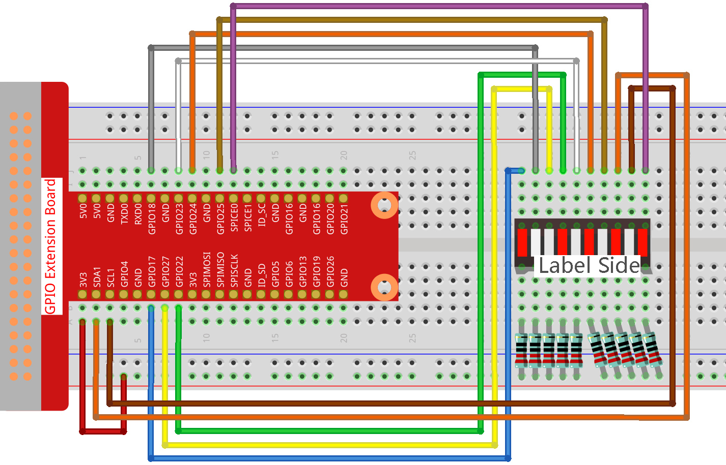
Step 1: Build the circuit.
Note
Pay attention to the direction when connecting. If you connect it backwards, it will not light up.
Step 2: Go to the folder of the code.
cd ~/raphael-kit/c/1.1.3/
Step 3: Compile the code.
gcc 1.1.3_LedBarGraph.c -lwiringPi
Step 4: Run the executable file.
sudo ./a.out
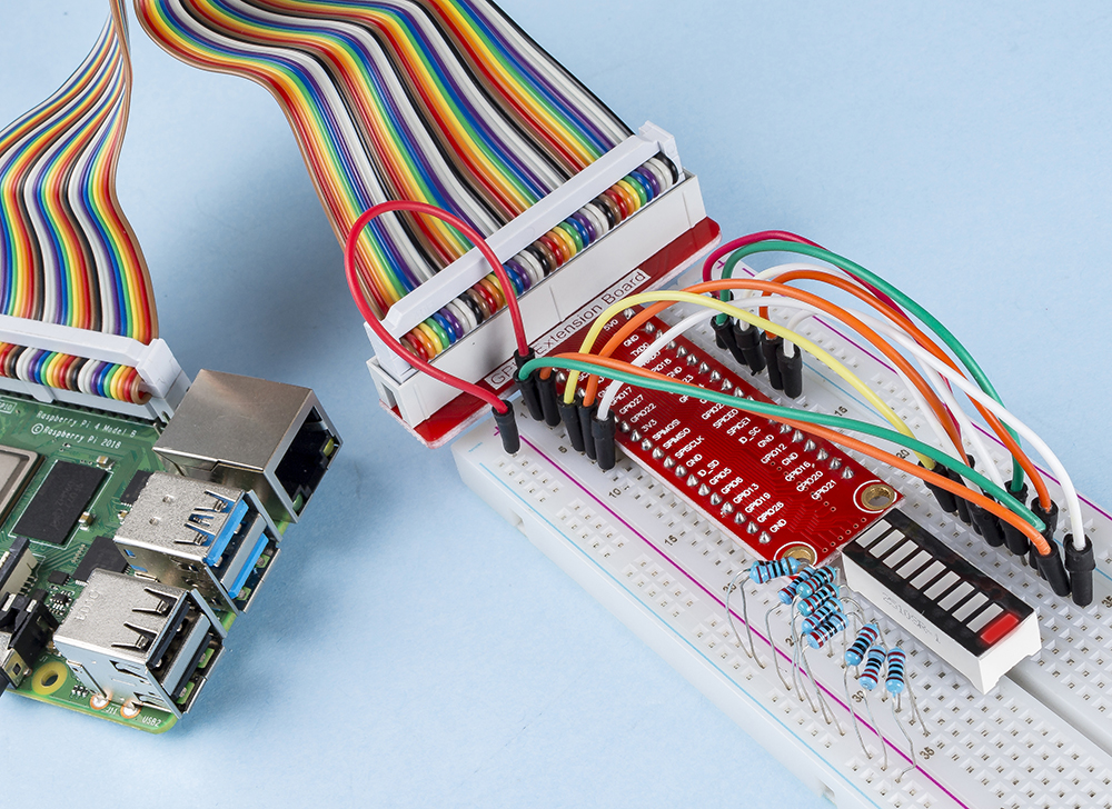
After the code runs, you will see the LEDs on the LED bar turn on and off regularly.
Note
If it does not work after running, or there is an error prompt: "wiringPi.h: No such file or directory", please refer to Install and Check the WiringPi.
Code
#include <wiringPi.h>
#include <stdio.h>

int pins[10] = {0,1,2,3,4,5,6,8,9,10};
void oddLedBarGraph(void){
    for(int i=0;i<5;i++){
        int j=i*2;
        digitalWrite(pins[j],HIGH);
        delay(300);
        digitalWrite(pins[j],LOW);
    }
}
void evenLedBarGraph(void){
    for(int i=0;i<5;i++){
        int j=i*2+1;
        digitalWrite(pins[j],HIGH);
        delay(300);
        digitalWrite(pins[j],LOW);
    }
}
void allLedBarGraph(void){
    for(int i=0;i<10;i++){
        digitalWrite(pins[i],HIGH);
        delay(300);
        digitalWrite(pins[i],LOW);
    }
}
int main(void)
{
    if(wiringPiSetup() == -1){ //when initialize wiring failed,print message to screen
        printf("setup wiringPi failed !");
        return 1;
    }
    for(int i=0;i<10;i++){       //make led pins' mode is output
        pinMode(pins[i], OUTPUT);
        digitalWrite(pins[i],LOW);
    }
    while(1){
        oddLedBarGraph();
        delay(300);
        evenLedBarGraph();
        delay(300);
        allLedBarGraph();
        delay(300);
    }
    return 0;
}
Code Explanation
int pins[10] = {0,1,2,3,4,5,6,8,9,10};
Create an array and assign it to the pin number corresponding to the LED Bar Graph (0,1,2,3,4,5,6,8,9,10) and the array will be used to control the LED.
void oddLedBarGraph(void){
    for(int i=0;i<5;i++){
        int j=i*2;
        digitalWrite(pins[j],HIGH);
        delay(300);
        digitalWrite(pins[j],LOW);
    }
}
Let the LED on the odd digit of the LED Bar Graph light on in turn.
void evenLedBarGraph(void){
    for(int i=0;i<5;i++){
        int j=i*2+1;
        digitalWrite(pins[j],HIGH);
        delay(300);
        digitalWrite(pins[j],LOW);
    }
}
Make the LED on the even digit of the LED Bar Graph light on in turn.
void allLedBarGraph(void){
    for(int i=0;i<10;i++){
        digitalWrite(pins[i],HIGH);
        delay(300);
        digitalWrite(pins[i],LOW);
    }
}
Let the LED on the LED Bar Graph light on one by one.
Phenomenon Picture