注釈
こんにちは、SunFounderのRaspberry Pi & Arduino & ESP32愛好家コミュニティへようこそ!Facebook上でRaspberry Pi、Arduino、ESP32についてもっと深く掘り下げ、他の愛好家と交流しましょう。
参加する理由は?
エキスパートサポート:コミュニティやチームの助けを借りて、販売後の問題や技術的な課題を解決します。
学び&共有:ヒントやチュートリアルを交換してスキルを向上させましょう。
独占的なプレビュー:新製品の発表や先行プレビューに早期アクセスしましょう。
特別割引:最新製品の独占割引をお楽しみください。
祭りのプロモーションとギフト:ギフトや祝日のプロモーションに参加しましょう。
👉 私たちと一緒に探索し、創造する準備はできていますか?[ここ]をクリックして今すぐ参加しましょう!
3.1.8 過熱モニター (MCP3008)
注釈
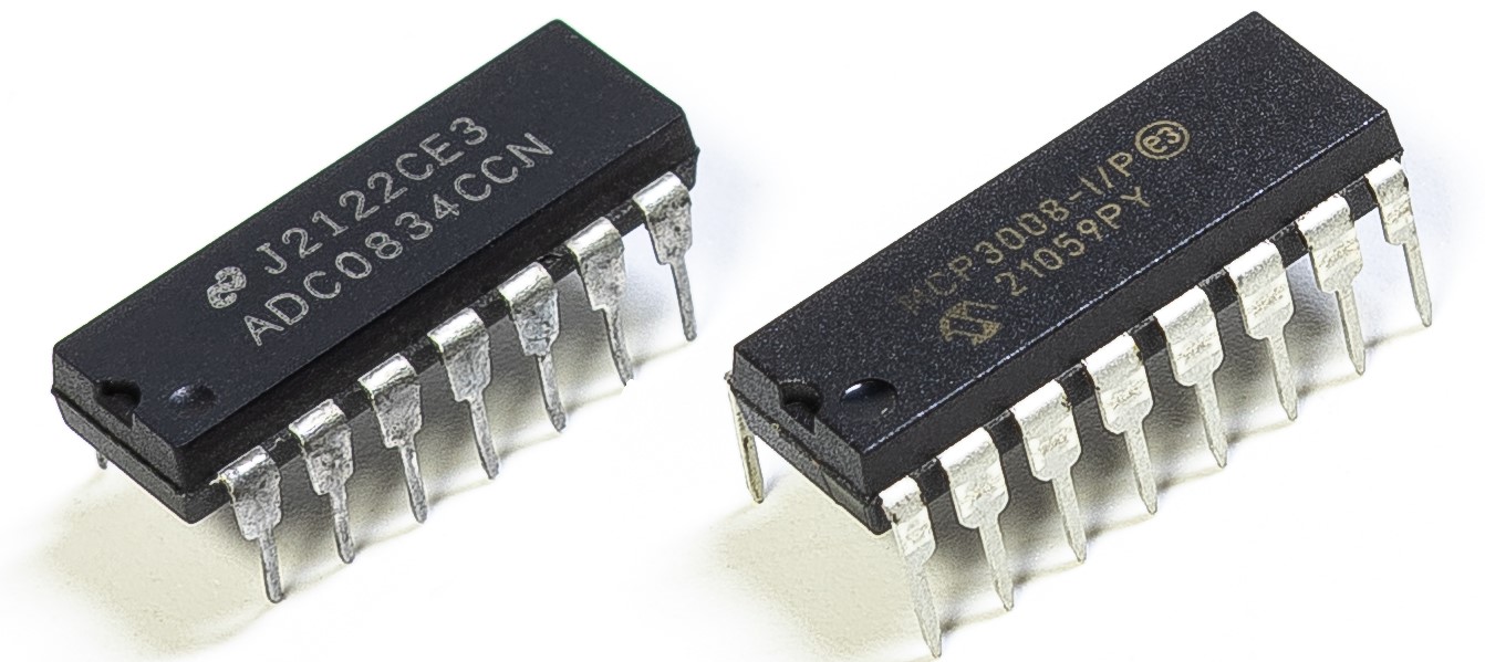
使用しているキットのバージョンによって、 ADC0834 か MCP3008 のどちらを搭載しているか確認し、それぞれ対応する節を参照してください。
導入
工場などの現場で回路が過熱した際、アラームを出し、適時に自動で機械を停止させたい場合があります。本プロジェクトでは、サーミスタ・ジョイスティック・ブザー・LED・LCD を利用し、しきい値を調整可能な温度監視装置を製作します。
必要な部品
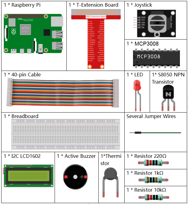
このプロジェクトでは以下の部品を使用します。
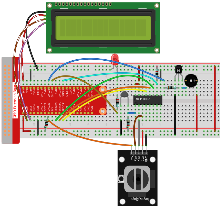
回路図
T-Board 名称 |
物理ピン |
wiringPi |
BCM |
SPICE0 |
Pin 24 |
10 |
8 |
SPIMOSI |
Pin 19 |
12 |
10 |
SPIMISO |
Pin 21 |
13 |
9 |
SPISCLK |
Pin 23 |
14 |
11 |
GPIO22 |
Pin15 |
3 |
22 |
GPIO23 |
Pin16 |
4 |
23 |
GPIO24 |
Pin18 |
5 |
24 |
SDA1 |
Pin 3 |
||
SCL1 |
Pin 5 |

実験手順
手順1: 回路を組み立てます。
C言語利用者向け
手順2: コードのあるフォルダに移動します。
cd ~/davinci-kit-for-raspberry-pi/c/3.1.8-2/
手順3: コードをコンパイルします。
gcc 3.1.8_OverheatMonitor.c -lm -lwiringPi
手順4: 実行ファイルを実行します。
sudo ./a.out
コードが実行されると、現在の温度と高温しきい値 40 が I2C LCD1602 に表示されます。現在の温度がしきい値を超えると、ブザーとLEDが動作して警告します。
ジョイスティック はしきい値を調整するために使用します。ジョイスティックをX軸またはY軸方向に倒すと、高温しきい値を上下に調整できます。ジョイスティックを再度押すと、しきい値は初期値にリセットされます。
注釈
wiringPi.h: No such file or directoryというエラーが出る場合は、wiringPi のインストールと確認 を参照してください。Unable to open I2C device: No such file or directoryというエラーが出る場合は、I²C 設定 を参照し、I2Cを有効化し配線が正しいか確認してください。コードと配線に問題がないのにLCDが表示されない場合は、背面のポテンショメータを回してコントラストを上げてください。
コード
#include <wiringPi.h>
#include <stdio.h>
#include <wiringPiI2C.h>
#include <wiringPiSPI.h>
#include <string.h>
#include <math.h>

typedef unsigned char uchar;
typedef unsigned int  uint;

#define Joy_BtnPin 3      // GPIO22 -> WiringPi 3
#define buzzPin    4      // GPIO23 -> WiringPi 4
#define LedPin     5      // GPIO24 -> WiringPi 5
#define SPI_CHANNEL 0
#define SPI_SPEED   1000000

int LCDAddr    = 0x27;
int BLEN       = 1;
int fd;
int upperTem   = 40;

// Global variable to store the last joystick change
int lastJoystickChange = 0;

int read_ADC(int channel) {
    if (channel < 0 || channel > 7) return -1;
    unsigned char buffer[3];
    buffer[0] = 1;
    buffer[1] = (8 + channel) << 4;
    buffer[2] = 0;
    wiringPiSPIDataRW(SPI_CHANNEL, buffer, 3);
    return ((buffer[1] & 0x03) << 8) | buffer[2];
}

void write_word(int data){
    int temp = data;
    if (BLEN)      temp |= 0x08;
    else           temp &= 0xF7;
    wiringPiI2CWrite(fd, temp);
}

void send_command(int comm){
    int buf = comm & 0xF0;
    buf |= 0x04; write_word(buf); delay(2); buf &= 0xFB; write_word(buf);
    buf = (comm & 0x0F) << 4;
    buf |= 0x04; write_word(buf); delay(2); buf &= 0xFB; write_word(buf);
}

void send_data(int data){
    int buf = data & 0xF0;
    buf |= 0x05; write_word(buf); delay(2); buf &= 0xFB; write_word(buf);
    buf = (data & 0x0F) << 4;
    buf |= 0x05; write_word(buf); delay(2); buf &= 0xFB; write_word(buf);
}

void lcd_init(){
    send_command(0x33); delay(5);
    send_command(0x32); delay(5);
    send_command(0x28); delay(5);
    send_command(0x0C); delay(5);
    send_command(0x01); wiringPiI2CWrite(fd, 0x08);
}

void lcd_clear(){
    send_command(0x01);
}

void write_lcd(int x, int y, const char data[]){
    int addr = 0x80 + 0x40 * y + x;
    send_command(addr);
    for (int i = 0; i < (int)strlen(data); i++)
        send_data(data[i]);
}

int get_joystick_value(){
    int x = read_ADC(1);
    int y = read_ADC(2);

    // Dead-band filtering to reduce small fluctuations
    if (x > 900)      return  1;   //    else if (x < 100) return -1;   //     else if (y > 900) return -10;  //     else if (y < 100) return  10;  //    else              return   0;
}

void upper_tem_setting(){
    write_lcd(0,0, "Upper Adjust:");

    int change = get_joystick_value();

    // Only respond to actual direction change
    if (change != 0 && change != lastJoystickChange) {
        upperTem += change;
        lastJoystickChange = change;
    }
    else if (change == 0) {
        // Allow next change after returning to center
        lastJoystickChange = 0;
    }

    // Display current upperTem
    char str[6];
    snprintf(str, sizeof(str), "%d", upperTem);
    write_lcd(0,1, str);
    // Clear remaining LCD characters
    write_lcd(strlen(str),1, "            ");

    delay(100);
}

double temperature(){
    int raw = read_ADC(0);
    double Vr = 3.3 * ((double)raw / 1023.0);
    double Rt = 10000.0 * Vr / (3.3 - Vr);
    double tempK = 1.0 / ((log(Rt/10000.0)/3950.0) + 1.0/(273.15+25.0));
    return tempK - 273.15;
}

void monitoring_temp(){
    char str[6];
    double cel = temperature();
    snprintf(str, sizeof(str), "%.2f", cel);
    write_lcd(0,0, "Temp: ");
    write_lcd(6,0, str);

    snprintf(str, sizeof(str), "%d", upperTem);
    write_lcd(0,1, "Upper: ");
    write_lcd(7,1, str);
    delay(100);

    if (cel >= upperTem) {
        digitalWrite(buzzPin, HIGH);
        digitalWrite(LedPin,  HIGH);
    } else {
        digitalWrite(buzzPin, LOW);
        digitalWrite(LedPin,  LOW);
    }
}

void setup_all(){
    fd = wiringPiI2CSetup(LCDAddr);
    lcd_init();
    if (wiringPiSetup() == -1 ||
        wiringPiSPISetup(SPI_CHANNEL, SPI_SPEED) == -1) {
        printf("Setup failed!\n");
        return;
    }
    pinMode(Joy_BtnPin, INPUT);
    pullUpDnControl(Joy_BtnPin, PUD_UP);
    pinMode(buzzPin, OUTPUT);
    pinMode(LedPin,  OUTPUT);
}

int main(void){
    setup_all();

    int lastBtnState = HIGH;
    int stage = 0;

    while (1) {
        int curBtn = digitalRead(Joy_BtnPin);
        // Switch mode when button changes from LOW to HIGH (button released)
        if (curBtn == HIGH && lastBtnState == LOW) {
            stage = (stage + 1) % 2;
            lastJoystickChange = 0;  // Clear debounce status
            delay(100);
            lcd_clear();
        }
        lastBtnState = curBtn;

        if (stage == 1)
            upper_tem_setting();
        else
            monitoring_temp();
    }

    return 0;
}
コード解説
int read_ADC(int channel) {
    if (channel < 0 || channel > 7) return -1;
    unsigned char buffer[3];
    buffer[0] = 1;
    buffer[1] = (8 + channel) << 4;
    buffer[2] = 0;
    wiringPiSPIDataRW(SPI_CHANNEL, buffer, 3);
    return ((buffer[1] & 0x03) << 8) | buffer[2];
}
SPIを使ってMCP3008のチャンネル (CH0–CH7) から10ビットのアナログ値を読み取り、0〜1023の整数を返します。
int get_joystick_value() {
    int x = read_ADC(1);
    int y = read_ADC(2);

    if (x > 900)      return 1;   // 右
    else if (x < 100) return -1;  // 左
    else if (y > 900) return -10; // 上
    else if (y < 100) return 10;  // 下
    else              return 0;
}
CH1とCH2からジョイスティックのX軸・Y軸のアナログ値を読み取ります。しきい値に基づき、動作方向を表す整数を返します。
void upper_tem_setting() {
    write_lcd(0,0, "Upper Adjust:");

    int change = get_joystick_value();

    if (change != 0 && change != lastJoystickChange) {
        upperTem += change;
        lastJoystickChange = change;
    }
    else if (change == 0) {
        lastJoystickChange = 0;
    }

    char str[6];
    snprintf(str, sizeof(str), "%d", upperTem);
    write_lcd(0,1, str);
    write_lcd(strlen(str),1, "            ");

    delay(100);
}
ジョイスティックを使って高温しきい値を調整します。方向を押し続けた場合でも、繰り返し変化しないよう制御します。
double temperature() {
    int raw = read_ADC(0);
    double Vr = 3.3 * ((double)raw / 1023.0);
    double Rt = 10000.0 * Vr / (3.3 - Vr);
    double tempK = 1.0 / ((log(Rt/10000.0)/3950.0) + 1.0/(273.15+25.0));
    return tempK - 273.15;
}
CH0に接続されたサーミスタのアナログ値を読み取ります。Steinhart–Hart方程式を用いて摂氏温度を計算します。
void monitoring_temp() {
    char str[6];
    double cel = temperature();
    snprintf(str, sizeof(str), "%.2f", cel);
    write_lcd(0,0, "Temp: ");
    write_lcd(6,0, str);

    snprintf(str, sizeof(str), "%d", upperTem);
    write_lcd(0,1, "Upper: ");
    write_lcd(7,1, str);
    delay(100);

    if (cel >= upperTem) {
        digitalWrite(buzzPin, HIGH);
        digitalWrite(LedPin,  HIGH);
    } else {
        digitalWrite(buzzPin, LOW);
        digitalWrite(LedPin,  LOW);
    }
}
現在の温度を継続的に読み取り、しきい値とともに表示します。温度がしきい値を超えた場合、ブザーとLEDを動作させます。
void setup_all() {
    fd = wiringPiI2CSetup(LCDAddr);
    lcd_init();
    if (wiringPiSetup() == -1 || wiringPiSPISetup(SPI_CHANNEL, SPI_SPEED) == -1) {
        printf("Setup failed!\n");
        return;
    }
    pinMode(Joy_BtnPin, INPUT);
    pullUpDnControl(Joy_BtnPin, PUD_UP);
    pinMode(buzzPin, OUTPUT);
    pinMode(LedPin,  OUTPUT);
}
LCD、SPI、GPIOピンを初期化します。ジョイスティックのボタンにはプルアップを設定し、ブザーとLEDも出力モードにします。
int main(void) {
    setup_all();

    int lastBtnState = HIGH;
    int stage = 0;

    while (1) {
        int curBtn = digitalRead(Joy_BtnPin);
        if (curBtn == HIGH && lastBtnState == LOW) {
            stage = (stage + 1) % 2;
            lastJoystickChange = 0;
            delay(100);
            lcd_clear();
        }
        lastBtnState = curBtn;

        if (stage == 1)
            upper_tem_setting();
        else
            monitoring_temp();
    }

    return 0;
}
メインループは2つのモードを切り替えます:
温度監視モード
ジョイスティックによる上限調整モード
ジョイスティックボタンを離したタイミング(立ち上がりエッジ)でモードが切り替わります。
Python言語利用者向け
手順2: SPIインターフェースを設定し、 spidev ライブラリをインストールします(詳細は SPI 設定 を参照)。すでに完了している場合、この手順は省略できます。
手順3: コードのあるフォルダに移動します。
cd ~/davinci-kit-for-raspberry-pi/python
手順4: 実行ファイルを実行します。
sudo python3 3.1.8-2_OverheatMonitor.py
コードが実行されると、現在の温度と高温しきい値 40 が I2C LCD1602 に表示されます。現在の温度がしきい値を超えると、ブザーとLEDが動作して警告します。
ジョイスティック は高温しきい値を調整するために使用します。X軸・Y軸方向に倒すことでしきい値を上下させられ、ボタンを押すと初期値にリセットされます。
注釈
FileNotFoundError: [Errno 2] No such file or directory: '/dev/i2c-1'が出る場合は、I²C 設定 を参照してI2Cを有効化してください。ModuleNotFoundError: No module named 'smbus2'が出る場合は、sudo pip3 install smbus2を実行してください。OSError: [Errno 121] Remote I/O errorが出る場合は、モジュールの配線間違いや故障が原因です。コードと配線に問題がなくてもLCDが表示しない場合、背面のポテンショメータを回してコントラストを上げてください。
警告
RuntimeError: Cannot determine SOC peripheral base address が出る場合は、「gpiozero」が動作しない場合。 を参照してください。
コード
注釈
以下のコードは 修正 / リセット / コピー / 実行 / 停止 が可能です。ただしその前に davinci-kit-for-raspberry-pi/python のソースコードパスへ移動する必要があります。コードを修正した後は、そのまま実行して動作を確認できます。
#!/usr/bin/env python3

import RPi.GPIO as GPIO
import spidev
import time
import math
import LCD1602

# GPIO pin definitions
JOY_BTN_PIN = 22  # Button pin
BUZZER_PIN = 23   # Buzzer pin
LED_PIN = 24      # LED pin

# Initialize GPIO
GPIO.setmode(GPIO.BCM)
GPIO.setup(JOY_BTN_PIN, GPIO.IN, pull_up_down=GPIO.PUD_UP)
GPIO.setup(BUZZER_PIN, GPIO.OUT)
GPIO.setup(LED_PIN, GPIO.OUT)

# Set initial upper temperature threshold
upperTem = 40

# Initialize SPI for MCP3008
spi = spidev.SpiDev()
spi.open(0, 0)
spi.max_speed_hz = 1000000  # 1 MHz

# Initialize LCD1602
LCD1602.init(0x27, 1)

def read_adc(channel):
    """
    Read analog value from MCP3008 (0–7)
    """
    if channel < 0 or channel > 7:
        return -1
    adc = spi.xfer2([1, (8 + channel) << 4, 0])
    value = ((adc[1] & 0x03) << 8) | adc[2]
    return value

def get_joystick_value():
    """
    Reads the joystick values and returns a change value based on the joystick's position.
    """
    x_val = read_adc(1)
    y_val = read_adc(2)
    if x_val > 800:
        return 1
    elif x_val < 200:
        return -1
    elif y_val > 800:
        return -10
    elif y_val < 200:
        return 10
    else:
        return 0

def upper_tem_setting():
    """
    Adjusts and displays the upper temperature threshold on the LCD.
    """
    global upperTem
    LCD1602.write(0, 0, 'Upper Adjust: ')
    change = int(get_joystick_value())
    upperTem += change
    strUpperTem = str(upperTem)
    LCD1602.write(0, 1, strUpperTem)
    LCD1602.write(len(strUpperTem), 1, '              ')
    time.sleep(0.1)

def temperature():
    """
    Reads the current temperature from the sensor and returns it in Celsius.
    """
    analogVal = read_adc(0)
    Vr = 3.3 * analogVal / 1023.0
    if Vr == 0:
        return 0
    Rt = 10000.0 * (3.3 - Vr) / Vr
    tempK = 1.0 / (((math.log(Rt / 10000.0)) / 3950.0) + (1.0 / (273.15 + 25.0)))
    Cel = tempK - 273.15
    return round(Cel, 2)

def monitoring_temp():
    """
    Monitors and displays the current temperature and upper temperature threshold.
    Activates buzzer and LED if the temperature exceeds the upper limit.
    """
    global upperTem
    Cel = temperature()
    LCD1602.write(0, 0, 'Temp: ')
    LCD1602.write(0, 1, 'Upper: ')
    LCD1602.write(6, 0, str(Cel))
    LCD1602.write(7, 1, str(upperTem))
    time.sleep(0.1)
    if Cel >= upperTem:
        GPIO.output(BUZZER_PIN, GPIO.HIGH)
        GPIO.output(LED_PIN, GPIO.HIGH)
    else:
        GPIO.output(BUZZER_PIN, GPIO.LOW)
        GPIO.output(LED_PIN, GPIO.LOW)

# Main loop
try:
    lastState = GPIO.input(JOY_BTN_PIN)
    stage = 0
    while True:
        currentState = GPIO.input(JOY_BTN_PIN)
        if currentState == GPIO.HIGH and lastState == GPIO.LOW:
            stage = (stage + 1) % 2
            time.sleep(0.1)
            LCD1602.clear()
        lastState = currentState

        if stage == 1:
            upper_tem_setting()
        else:
            monitoring_temp()

except KeyboardInterrupt:
    pass

finally:
    LCD1602.clear()
    GPIO.cleanup()
    spi.close()
コード解説
ライブラリのインポート
GPIO、SPI、LCD表示、時間制御、数値計算に必要なライブラリを読み込みます。
#!/usr/bin/env python3
import RPi.GPIO as GPIO
import spidev
import time
import math
import LCD1602
GPIOとデバイス設定
ジョイスティックのボタン、ブザー、LED のGPIOピンを定義し、GPIOモードを設定します。
JOY_BTN_PIN = 22  # ボタンのピン
BUZZER_PIN = 23   # ブザーのピン
LED_PIN = 24      # LEDのピン

GPIO.setmode(GPIO.BCM)
GPIO.setup(JOY_BTN_PIN, GPIO.IN, pull_up_down=GPIO.PUD_UP)
GPIO.setup(BUZZER_PIN, GPIO.OUT)
GPIO.setup(LED_PIN, GPIO.OUT)
SPIとLCDの初期化
MCP3008用のSPIインターフェースを開始し、I2Cアドレス 0x27 のLCD1602画面を初期化します。
upperTem = 40
spi = spidev.SpiDev()
spi.open(0, 0)
spi.max_speed_hz = 1000000

LCD1602.init(0x27, 1)
ADC値の読み取り
SPIを介してMCP3008からアナログデータを読み取ります。チャンネルは0〜7の範囲で指定します。
def read_adc(channel):
    if channel < 0 or channel > 7:
        return -1
    adc = spi.xfer2([1, (8 + channel) << 4, 0])
    value = ((adc[1] & 0x03) << 8) | adc[2]
    return value
ジョイスティックの動き検出
ジョイスティックのX軸・Y軸値を読み取り、しきい値の変更量を返します。
def get_joystick_value():
    x_val = read_adc(1)
    y_val = read_adc(2)
    if x_val > 800:
        return 1
    elif x_val < 200:
        return -1
    elif y_val > 800:
        return -10
    elif y_val < 200:
        return 10
    else:
        return 0
上限温度しきい値の調整
LCDに「Upper Adjust」を表示し、ジョイスティック入力でしきい値を調整します。
def upper_tem_setting():
    global upperTem
    LCD1602.write(0, 0, 'Upper Adjust: ')
    change = int(get_joystick_value())
    upperTem += change
    strUpperTem = str(upperTem)
    LCD1602.write(0, 1, strUpperTem)
    LCD1602.write(len(strUpperTem), 1, '              ')
    time.sleep(0.1)
温度計算
アナログセンサー値を電圧と抵抗に変換し、Steinhart–Hart近似式で摂氏温度を算出します。
def temperature():
    analogVal = read_adc(0)
    Vr = 3.3 * analogVal / 1023.0
    if Vr == 0:
        return 0
    Rt = 10000.0 * (3.3 - Vr) / Vr
    tempK = 1.0 / (((math.log(Rt / 10000.0)) / 3950.0) + (1.0 / (273.15 + 25.0)))
    Cel = tempK - 273.15
    return round(Cel, 2)
温度モニタリング
現在温度としきい値を継続的に確認し表示します。温度がしきい値を超えるとブザーとLEDを点灯させます。
def monitoring_temp():
    global upperTem
    Cel = temperature()
    LCD1602.write(0, 0, 'Temp: ')
    LCD1602.write(0, 1, 'Upper: ')
    LCD1602.write(6, 0, str(Cel))
    LCD1602.write(7, 1, str(upperTem))
    time.sleep(0.1)
    if Cel >= upperTem:
        GPIO.output(BUZZER_PIN, GPIO.HIGH)
        GPIO.output(LED_PIN, GPIO.HIGH)
    else:
        GPIO.output(BUZZER_PIN, GPIO.LOW)
        GPIO.output(LED_PIN, GPIO.LOW)
メイン処理の流れ
ジョイスティックのボタンが押されたとき、温度モニタリングモードとしきい値調整モードを切り替えます。
try:
    lastState = GPIO.input(JOY_BTN_PIN)
    stage = 0
    while True:
        currentState = GPIO.input(JOY_BTN_PIN)
        if currentState == GPIO.HIGH and lastState == GPIO.LOW:
            stage = (stage + 1) % 2
            time.sleep(0.1)
            LCD1602.clear()
        lastState = currentState

        if stage == 1:
            upper_tem_setting()
        else:
            monitoring_temp()
終了時の後処理
Ctrl+Cで終了した際、GPIOとSPIリソースを正しく解放します。
except KeyboardInterrupt:
    pass
finally:
    LCD1602.clear()
    GPIO.cleanup()
    spi.close()