注釈
こんにちは、SunFounderのRaspberry Pi & Arduino & ESP32愛好家コミュニティへようこそ!Facebook上でRaspberry Pi、Arduino、ESP32についてもっと深く掘り下げ、他の愛好家と交流しましょう。
参加する理由は?
エキスパートサポート:コミュニティやチームの助けを借りて、販売後の問題や技術的な課題を解決します。
学び&共有:ヒントやチュートリアルを交換してスキルを向上させましょう。
独占的なプレビュー:新製品の発表や先行プレビューに早期アクセスしましょう。
特別割引:最新製品の独占割引をお楽しみください。
祭りのプロモーションとギフト:ギフトや祝日のプロモーションに参加しましょう。
👉 私たちと一緒に探索し、創造する準備はできていますか?[ここ]をクリックして今すぐ参加しましょう!
3.1.7 信号機
前書き
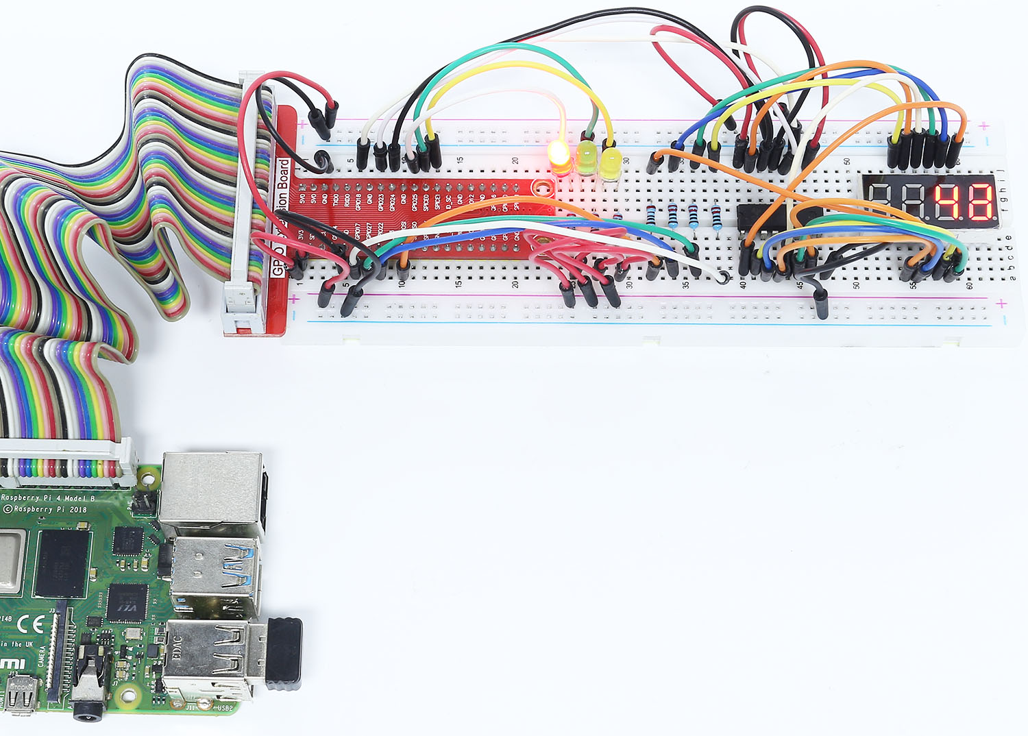
このプロジェクトでは、3色のLEDを使用して交通信号の変化を実現し、 4桁の7セグメントディスプレイを使用して各交通状態のタイミングを表示する。
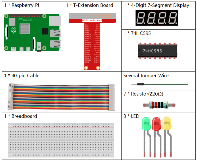
部品
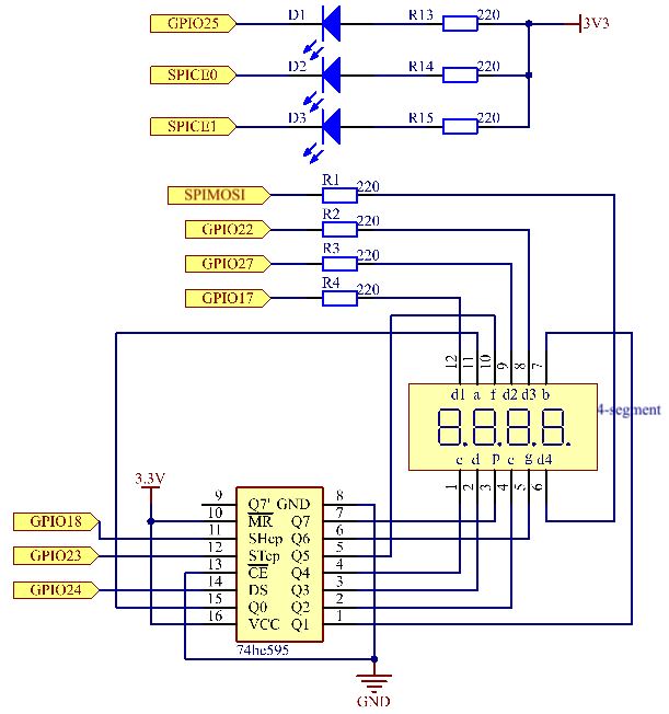
回路図
T-Board Name |
physical |
wiringPi |
BCM |
GPIO17 |
Pin 11 |
0 |
17 |
GPIO27 |
Pin 13 |
2 |
27 |
GPIO22 |
Pin 15 |
3 |
22 |
SPIMOSI |
Pin 19 |
12 |
10 |
GPIO18 |
Pin 12 |
1 |
18 |
GPIO23 |
Pin 16 |
4 |
23 |
GPIO24 |
Pin 18 |
5 |
24 |
GPIO25 |
Pin 22 |
6 |
25 |
SPICE0 |
Pin 24 |
10 |
8 |
SPICE1 |
Pin 26 |
11 |
7 |
実験手順
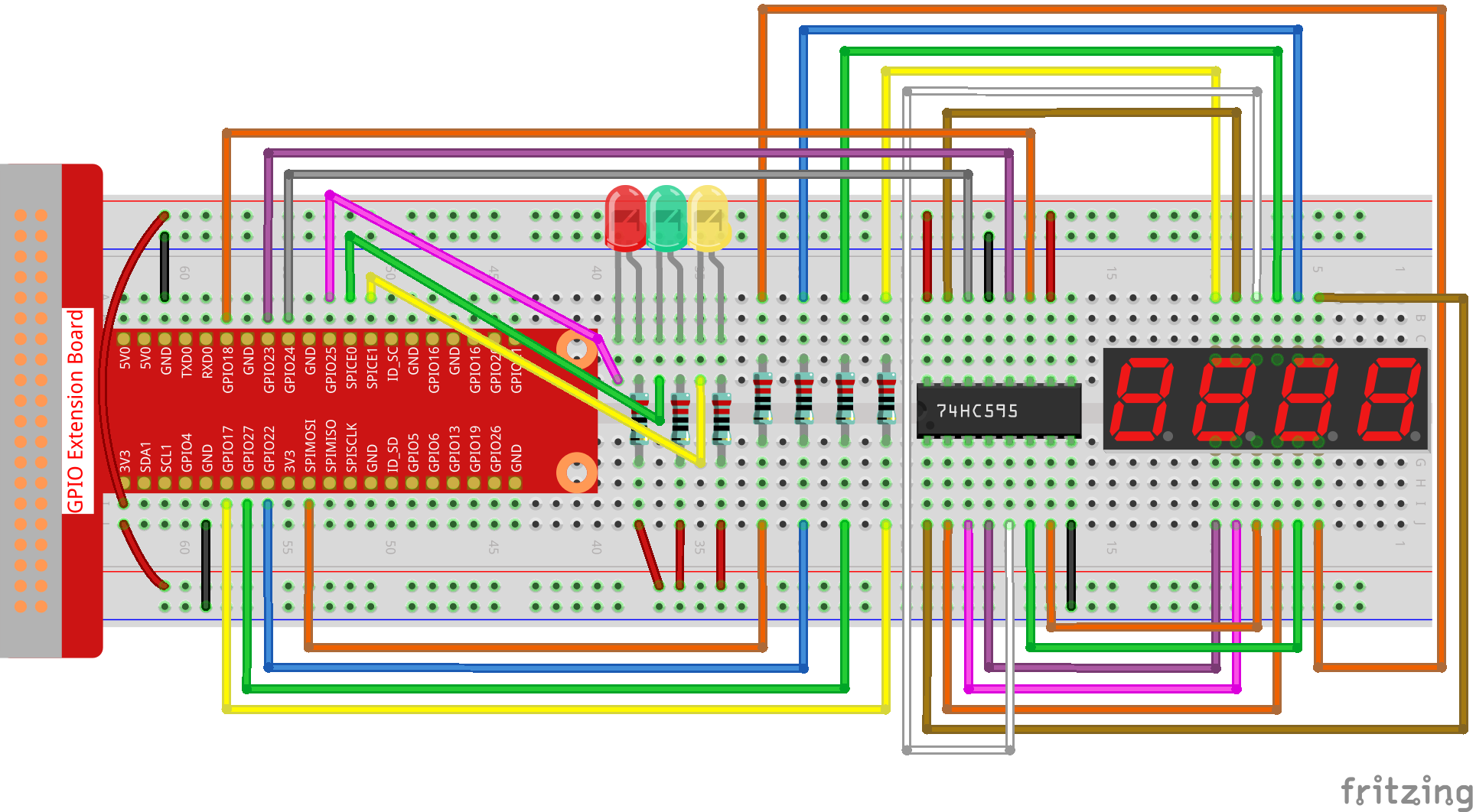
ステップ1: 回路を作る。
C言語ユーザー向け
ステップ2: ディレクトリを変更する。
cd ~/davinci-kit-for-raspberry-pi/c/3.1.7/
ステップ3: コンパイルする。
gcc 3.1.7_TrafficLight.c -lwiringPi
ステップ4: 実行する。
sudo ./a.out
コードが実行されると、LEDは交通信号の色の変化をシミュレートする。 まず、赤色のLEDが60秒間点灯し、それから緑色のLEDが30秒間点灯し、最後に、黄色のLEDが5秒間点灯する。 その後、赤いLEDが60秒間再び点灯する。 このようにして、この一連のアクションは繰り返し実行される。
コードの説明
#define     SDI     5
#define     RCLK    4
#define     SRCLK    1

const int placePin[] = {12, 3, 2, 0};
unsigned char number[] = {0xc0, 0xf9, 0xa4, 0xb0, 0x99, 0x92, 0x82, 0xf8, 0x80, 0x90};

void pickDigit(int digit);
void hc595_shift(int8_t data);
void clearDisplay();
void display();
これらのコードは、4桁7セグメントディスプレイの数値表示機能を実現するために使用されます。 詳細については、ドキュメントの 1.1.5 4桁7セグメントディスプレイ を参照してください。 ここでは、コードを使用して信号時間のカウントダウンを表示します。
const int ledPin[]={6,10,11};

int colorState = 0;

void lightup()
{
    for(int i=0;i<3;i++){
        digitalWrite(ledPin[i],HIGH);
    }
    digitalWrite(ledPin[colorState],LOW);
}
コードはLEDのオンとオフを切り替えるために使用される。
int greenLight = 30;
int yellowLight = 5;
int redLight = 60;
int colorState = 0;
char *lightColor[]={"Red","Green","Yellow"};
int counter = 60;

void timer(int  timer1){       //Timer function
    if(timer1 == SIGALRM){
        counter --;
        alarm(1);
        if(counter == 0){
            if(colorState == 0) counter = greenLight;
            if(colorState == 1) counter = yellowLight;
            if(colorState == 2) counter = redLight;
            colorState = (colorState+1)%3;
        }
        printf("counter : %d \t light color: %s \n",counter,lightColor[colorState]);
    }
}
コードは、タイマーのオンとオフを切り替えるために使用されます。 詳細については、 1.1.5 4桁7セグメントディスプレイ を参照してください。 ここで、タイマーがゼロに戻ると、 colorState が切り替えられてLEDが切り替わり、タイマーが新しい値に割り当てられます。
void loop()
{
    while(1){
    display();
    lightup();
    }
}

int main(void)
{
    //…
    signal(SIGALRM,timer);
    alarm(1);
    loop();
    return 0;
}
タイマーは main() 関数で始まる。
loop() 関数では、 while(1) loopを使用して、4桁7セグメントとLEDの関数を呼び出す。
Python言語ユーザー向け
ステップ2: ディレクトリを変更する。
cd ~/davinci-kit-for-raspberry-pi/python/
ステップ3: 実行する。
sudo python3 3.1.7_TrafficLight.py
コードが実行されると、LEDは交通信号の色の変化をシミュレートする。 まず、赤色のLEDが60秒間点灯し、それから緑色のLEDが30秒間点灯し、最後に、黄色のLEDが5秒間点灯する。 その後、赤いLEDが60秒間再び点灯する。このようにして、この一連のアクションは繰り返し実行される。 一方、4桁の7セグメントディスプレイには、カウントダウン時間が連続して表示される。
コード
注釈
以下のコードを 変更/リセット/コピー/実行/停止 できます。 ただし、その前に、 davinci-kit-for-raspberry-pi/python のようなソースコードパスに移動する必要があります。
import RPi.GPIO as GPIO
import time
import threading

#define the pins connect to 74HC595
SDI   = 24      #serial data input(DS)
RCLK  = 23     #memory clock input(STCP)
SRCLK = 18      #shift register clock input(SHCP)
number = (0xc0,0xf9,0xa4,0xb0,0x99,0x92,0x82,0xf8,0x80,0x90)

placePin = (10,22,27,17)
ledPin =(25,8,7)

greenLight = 30
yellowLight = 5
redLight = 60
lightColor=("Red","Green","Yellow")

colorState=0
counter = 60
timer1 = 0


def setup():
    GPIO.setmode(GPIO.BCM)
    GPIO.setup(SDI, GPIO.OUT)
    GPIO.setup(RCLK, GPIO.OUT)
    GPIO.setup(SRCLK, GPIO.OUT)
    for pin in placePin:
        GPIO.setup(pin,GPIO.OUT)
    for pin in ledPin:
        GPIO.setup(pin,GPIO.OUT)
    global timer1
    timer1 = threading.Timer(1.0,timer)
    timer1.start()

def clearDisplay():
    for i in range(8):
        GPIO.output(SDI, 1)
        GPIO.output(SRCLK, GPIO.HIGH)
        GPIO.output(SRCLK, GPIO.LOW)
    GPIO.output(RCLK, GPIO.HIGH)
    GPIO.output(RCLK, GPIO.LOW)

def hc595_shift(data):
    for i in range(8):
        GPIO.output(SDI, 0x80 & (data << i))
        GPIO.output(SRCLK, GPIO.HIGH)
        GPIO.output(SRCLK, GPIO.LOW)
    GPIO.output(RCLK, GPIO.HIGH)
    GPIO.output(RCLK, GPIO.LOW)

def pickDigit(digit):
    for i in placePin:
        GPIO.output(i,GPIO.LOW)
    GPIO.output(placePin[digit], GPIO.HIGH)

def timer():        #timer function
    global counter
    global colorState
    global timer1
    timer1 = threading.Timer(1.0,timer)
    timer1.start()
    counter-=1
    if (counter is 0):
        if(colorState is 0):
            counter= greenLight
        if(colorState is 1):
            counter=yellowLight
        if (colorState is 2):
            counter=redLight
        colorState=(colorState+1)%3
    print ("counter : %d    color: %s "%(counter,lightColor[colorState]))

def lightup():
    global colorState
    for i in range(0,3):
        GPIO.output(ledPin[i], GPIO.HIGH)
    GPIO.output(ledPin[colorState], GPIO.LOW)

def display():
    global counter

    a = counter % 10000//1000 + counter % 1000//100
    b = counter % 10000//1000 + counter % 1000//100 + counter % 100//10
    c = counter % 10000//1000 + counter % 1000//100 + counter % 100//10 + counter % 10

    if (counter % 10000//1000 == 0):
        clearDisplay()
    else:
        clearDisplay()
        pickDigit(3)
        hc595_shift(number[counter % 10000//1000])

    if (a == 0):
        clearDisplay()
    else:
        clearDisplay()
        pickDigit(2)
        hc595_shift(number[counter % 1000//100])

    if (b == 0):
        clearDisplay()
    else:
        clearDisplay()
        pickDigit(1)
        hc595_shift(number[counter % 100//10])

    if(c == 0):
        clearDisplay()
    else:
        clearDisplay()
        pickDigit(0)
        hc595_shift(number[counter % 10])

def loop():
    while True:
        display()
        lightup()

def destroy():   # When "Ctrl+C" is pressed, the function is executed.
    global timer1
    GPIO.cleanup()
    timer1.cancel()      #cancel the timer

if __name__ == '__main__': # Program starting from here
    setup()
    try:
        loop()
    except KeyboardInterrupt:
        destroy()
コードの説明
SDI   = 24      #serial data input(DS)
RCLK  = 23     #memory clock input(STCP)
SRCLK = 18      #shift register clock input(SHCP)
number = (0xc0,0xf9,0xa4,0xb0,0x99,0x92,0x82,0xf8,0x80,0x90)
placePin = (10,22,27,17)

def clearDisplay():
def hc595_shift(data):
def pickDigit(digit):
def display():
これらのコードは、4桁7セグメントの数値表示機能を実現するために使用されます。 詳細については、ドキュメントの 1.1.5 4桁7セグメントディスプレイ を参照してください。 ここでは、コードを使用して信号時間のカウントダウンを表示します。
ledPin =(25,8,7)
colorState=0

def lightup():
    global colorState
    for i in range(0,3):
        GPIO.output(ledPin[i], GPIO.HIGH)
    GPIO.output(ledPin[colorState], GPIO.LOW)
コードはLEDのオンとオフを切り替えるために使用される。
greenLight = 30
yellowLight = 5
redLight = 60
lightColor=("Red","Green","Yellow")

colorState=0
counter = 60
timer1 = 0

def timer():        #timer function
    global counter
    global colorState
    global timer1
    timer1 = threading.Timer(1.0,timer)
    timer1.start()
    counter-=1
    if (counter is 0):
        if(colorState is 0):
            counter= greenLight
        if(colorState is 1):
            counter=yellowLight
        if (colorState is 2):
            counter=redLight
        colorState=(colorState+1)%3
    print ("counter : %d    color: %s "%(counter,lightColor[colorState]))
コードは、タイマーのオンとオフを切り替えるために使用されます。
詳細については、 1.1.5 4桁7セグメントディスプレイ を参照してください。
ここで、タイマーがゼロに戻ると、
colorState が切り替えられてLEDが切り替わり、タイマーが新しい値に割り当てられます。
def setup():
    # ...
    global timer1
    timer1 = threading.Timer(1.0,timer)
    timer1.start()

def loop():
    while True:
        display()
        lightup()

def destroy():   # When "Ctrl+C" is pressed, the function is executed.
    global timer1
    GPIO.cleanup()
    timer1.cancel()      #cancel the timer

if __name__ == '__main__': # Program starting from here
    setup()
    try:
        loop()
    except KeyboardInterrupt:
        destroy()
setup() 関数で、タイマーを開始する。
loop() 関数では、 while True が使用される:4-桁の7-セグメントとLEDの相対関数を循環的に呼び出す。
現象画像