Note
Hello, welcome to the SunFounder Raspberry Pi & Arduino & ESP32 Enthusiasts Community on Facebook! Dive deeper into Raspberry Pi, Arduino, and ESP32 with fellow enthusiasts.
Why Join?
Expert Support: Solve post-sale issues and technical challenges with help from our community and team.
Learn & Share: Exchange tips and tutorials to enhance your skills.
Exclusive Previews: Get early access to new product announcements and sneak peeks.
Special Discounts: Enjoy exclusive discounts on our newest products.
Festive Promotions and Giveaways: Take part in giveaways and holiday promotions.
👉 Ready to explore and create with us? Click [here] and join today!
3.1.8 Overheat Monitor(MCP3008)
Note
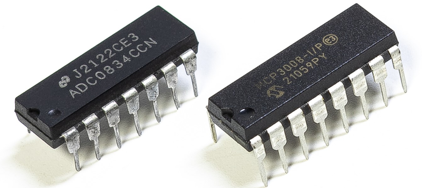
Depending on your kit version, please identify whether you have ADC0834 or MCP3008 and proceed with the matching section.
Introduction
You may want to make an overheat monitoring device that applies to various situations, ex., in the factory, if we want to have an alarm and the timely automatic turning off of the machine when there is a circuit overheating. In this project, we will use thermistor, joystick, buzzer, LED and LCD to make an smart temperature monitoring device whose threshold is adjustable.
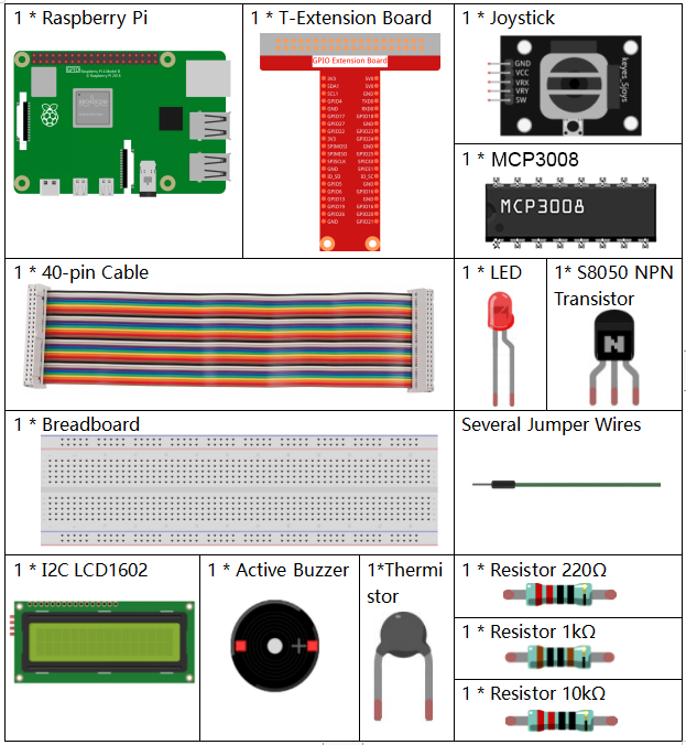
Required Components
In this project, we need the following components.
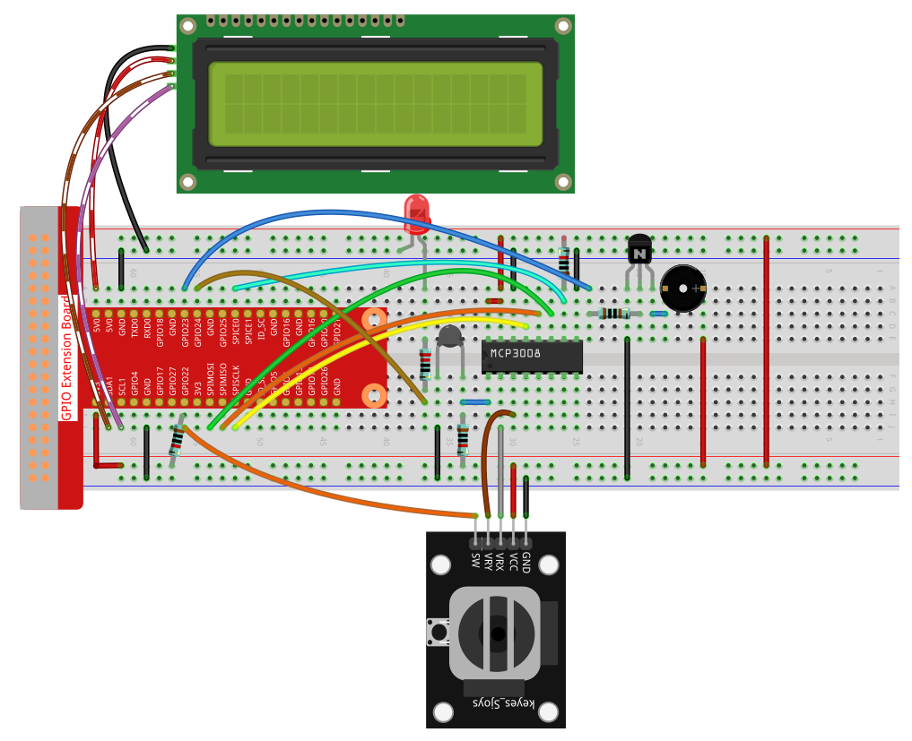
Schematic Diagram
T-Board Name |
physical |
wiringPi |
BCM |
SPICE0 |
Pin 24 |
10 |
8 |
SPIMOSI |
Pin 19 |
12 |
10 |
SPIMISO |
Pin 21 |
13 |
9 |
SPISCLK |
Pin 23 |
14 |
11 |
GPIO22 |
Pin15 |
3 |
22 |
GPIO23 |
Pin16 |
4 |
23 |
GPIO24 |
Pin18 |
5 |
24 |
SDA1 |
Pin 3 |
||
SCL1 |
Pin 5 |

Experimental Procedures
Step 1: Build the circuit.
Step 2: Set up the SPI interface and install the spidev library (see SPI Configuration for detailed instructions). If you have already completed these steps, you can skip this.
Step 3: Go to the folder of the code.
cd ~/davinci-kit-for-raspberry-pi/python-pi5
Step 4: Run the executable file.
sudo python3 3.1.8-2_OverheatMonitor_zero.py
As the code runs, the current temperature and the high-temperature threshold 40 are displayed on I2C LCD1602. If the current temperature is larger than the threshold, the buzzer and LED are started to alarm you.
Joystick here is for your pressing to adjust the high-temperature threshold. Toggling the Joystick in the direction of X-axis and Y-axis can adjust (turn up or down) the current high-temperature threshold. Press the Joystick once again to reset the threshold to initial value.
Note
If you get the error
FileNotFoundError: [Errno 2] No such file or directory: '/dev/i2c-1', you need to refer to I²C Configuration to enable the I2C.If you get
ModuleNotFoundError: No module named 'smbus2'error, please runsudo apt install python3-smbus2.If the error
OSError: [Errno 121] Remote I/O errorappears, it means the module is miswired or the module is broken.If the code and wiring are fine, but the LCD still does not display content, you can turn the potentiometer on the back to increase the contrast.
Warning
If there is an error prompt RuntimeError: Cannot determine SOC peripheral base address, please refer to If gpiozero doesn’t work.
Code
Note
You can Modify/Reset/Copy/Run/Stop the code below. But before that, you need to go to source code path like davinci-kit-for-raspberry-pi/python. After modifying the code, you can run it directly to see the effect.
#!/usr/bin/env python3

import LCD1602
from gpiozero import LED, Buzzer, Button
import spidev
import time
import math

# Initialize joystick button, buzzer, and LED
Joy_BtnPin = Button(22)  # GPIO22, Pin15
buzzPin = Buzzer(23)     # GPIO23, Pin16
ledPin = LED(24)         # GPIO24, Pin18

# Set initial upper temperature threshold
upperTem = 40

# Initialize SPI for MCP3008 (Bus 0, CE0 -> GPIO8 / Pin24)
spi = spidev.SpiDev()
spi.open(0, 0)
spi.max_speed_hz = 1000000  # 1 MHz

# Initialize LCD (I2C address 0x27, backlight on)
LCD1602.init(0x27, 1)

def read_adc(channel):
    """
    Read analog value from MCP3008 (0–7)
    """
    if channel < 0 or channel > 7:
        return -1
    adc = spi.xfer2([1, (8 + channel) << 4, 0])
    value = ((adc[1] & 0x03) << 8) | adc[2]
    return value

def get_joystick_value():
    """
    Reads the joystick values and returns a change value based on the joystick's position.
    """
    x_val = read_adc(1)
    y_val = read_adc(2)
    if x_val > 800:
        return 1
    elif x_val < 200:
        return -1
    elif y_val > 800:
        return -10
    elif y_val < 200:
        return 10
    else:
        return 0

def upper_tem_setting():
    """
    Adjusts and displays the upper temperature threshold on the LCD.
    """
    global upperTem
    LCD1602.write(0, 0, 'Upper Adjust: ')
    change = int(get_joystick_value())
    upperTem += change
    strUpperTem = str(upperTem)
    LCD1602.write(0, 1, strUpperTem)
    LCD1602.write(len(strUpperTem), 1, '              ')
    time.sleep(0.1)

def temperature():
    """
    Reads the current temperature from the sensor and returns it in Celsius.
    """
    analogVal = read_adc(0)
    Vr = 3.3 * analogVal / 1023.0  # Voltage across the fixed resistor
    if Vr == 0:
        return 0  # Prevent division by zero
    Rt = 10000.0 * Vr / (3.3 - Vr)  # Adjusted formula: thermistor voltage is (3.3 - Vr)
    temp = 1 / (((math.log(Rt / 10000.0)) / 3950.0) + (1 / (273.15 + 25.0)))
    Cel = temp - 273.15
    return round(Cel, 2)

def monitoring_temp():
    """
    Monitors and displays the current temperature and upper temperature threshold.
    Activates buzzer and LED if the temperature exceeds the upper limit.
    """
    global upperTem
    Cel = temperature()
    LCD1602.write(0, 0, 'Temp: ')
    LCD1602.write(0, 1, 'Upper: ')
    LCD1602.write(6, 0, str(Cel))
    LCD1602.write(7, 1, str(upperTem))
    time.sleep(0.1)
    if Cel >= upperTem:
        buzzPin.on()
        ledPin.on()
    else:
        buzzPin.off()
        ledPin.off()

# Main execution loop
try:
    lastState = 1
    stage = 0
    while True:
        currentState = Joy_BtnPin.value
        if currentState == 1 and lastState == 0:
            stage = (stage + 1) % 2
            time.sleep(0.1)
            LCD1602.clear()
        lastState = currentState
        if stage == 1:
            upper_tem_setting()
        else:
            monitoring_temp()
except KeyboardInterrupt:
    LCD1602.clear()
    spi.close()
Code Explanation
This section imports the required libraries.
LCD1602is for LCD display via I2C,gpiozeroprovides support for the LED, Buzzer, and Button,spidevis used to communicate with the MCP3008 ADC, and standardtimeandmathlibraries are used for delays and temperature calculations.#!/usr/bin/env python3 import LCD1602 from gpiozero import LED, Buzzer, Button import spidev import time import math
Initializes hardware components connected to GPIO pins:
Button(22)connects to the joystick button.Buzzer(23)andLED(24)serve as output indicators for high temperature.
Joy_BtnPin = Button(22)  # GPIO22, Pin15
buzzPin = Buzzer(23)     # GPIO23, Pin16
ledPin = LED(24)         # GPIO24, Pin18
Sets the default upper temperature threshold and initializes both SPI for MCP3008 and the LCD1602 display.
upperTem = 40

spi = spidev.SpiDev()
spi.open(0, 0)
spi.max_speed_hz = 1000000

LCD1602.init(0x27, 1)
This function reads the analog value from a specified channel (0–7) on the MCP3008 using SPI protocol and returns a 10-bit value.
def read_adc(channel):
    if channel < 0 or channel > 7:
        return -1
    adc = spi.xfer2([1, (8 + channel) << 4, 0])
    value = ((adc[1] & 0x03) << 8) | adc[2]
    return value
The joystick’s position is evaluated by reading channels 1 and 2 of the MCP3008. Depending on X or Y direction, different values are returned for threshold adjustments.
def get_joystick_value():
    x_val = read_adc(1)
    y_val = read_adc(2)
    if x_val > 800:
        return 1
    elif x_val < 200:
        return -1
    elif y_val > 800:
        return -10
    elif y_val < 200:
        return 10
    else:
        return 0
Adjusts the upper temperature threshold using the joystick. Displays the current threshold on the LCD and ensures clean formatting.
def upper_tem_setting():
    global upperTem
    LCD1602.write(0, 0, 'Upper Adjust: ')
    change = int(get_joystick_value())
    upperTem += change
    strUpperTem = str(upperTem)
    LCD1602.write(0, 1, strUpperTem)
    LCD1602.write(len(strUpperTem), 1, '              ')
    time.sleep(0.1)
This function reads the analog value from MCP3008 channel 0 (connected to a thermistor), calculates voltage, resistance, and ultimately the temperature in Celsius using the Steinhart–Hart approximation.
def temperature():
    """
    Reads the current temperature from the sensor and returns it in Celsius.
    """
    analogVal = read_adc(0)
    Vr = 3.3 * analogVal / 1023.0  # Voltage across the fixed resistor
    if Vr == 0:
        return 0  # Prevent division by zero
    Rt = 10000.0 * Vr / (3.3 - Vr)  # Adjusted formula: thermistor voltage is (3.3 - Vr)
    temp = 1 / (((math.log(Rt / 10000.0)) / 3950.0) + (1 / (273.15 + 25.0)))
    Cel = temp - 273.15
    return round(Cel, 2)
Continuously reads the current temperature, compares it with the upper threshold, and displays both on the LCD. If the temperature exceeds the threshold, the buzzer and LED are turned on.
def monitoring_temp():
    global upperTem
    Cel = temperature()
    LCD1602.write(0, 0, 'Temp: ')
    LCD1602.write(0, 1, 'Upper: ')
    LCD1602.write(6, 0, str(Cel))
    LCD1602.write(7, 1, str(upperTem))
    time.sleep(0.1)
    if Cel >= upperTem:
        buzzPin.on()
        ledPin.on()
    else:
        buzzPin.off()
        ledPin.off()
The main execution loop alternates between setting mode and monitoring mode using a joystick button. A press toggles the mode. In setting mode, the upper threshold is adjusted; in monitoring mode, temperature is continuously checked.
try:
    lastState = 1
    stage = 0
    while True:
        currentState = Joy_BtnPin.value
        if currentState == 1 and lastState == 0:
            stage = (stage + 1) % 2
            time.sleep(0.1)
            LCD1602.clear()
        lastState = currentState
        if stage == 1:
            upper_tem_setting()
        else:
            monitoring_temp()
Ensures that the LCD is cleared and SPI communication is properly closed when the program exits via keyboard interruption.
except KeyboardInterrupt:
    LCD1602.clear()
    spi.close()