Note
Hello, welcome to the SunFounder Raspberry Pi & Arduino & ESP32 Enthusiasts Community on Facebook! Dive deeper into Raspberry Pi, Arduino, and ESP32 with fellow enthusiasts.
Why Join?
Expert Support: Solve post-sale issues and technical challenges with help from our community and team.
Learn & Share: Exchange tips and tutorials to enhance your skills.
Exclusive Previews: Get early access to new product announcements and sneak peeks.
Special Discounts: Enjoy exclusive discounts on our newest products.
Festive Promotions and Giveaways: Take part in giveaways and holiday promotions.
👉 Ready to explore and create with us? Click [here] and join today!
3.1.5 Battery Indicator(MCP3008)
Note
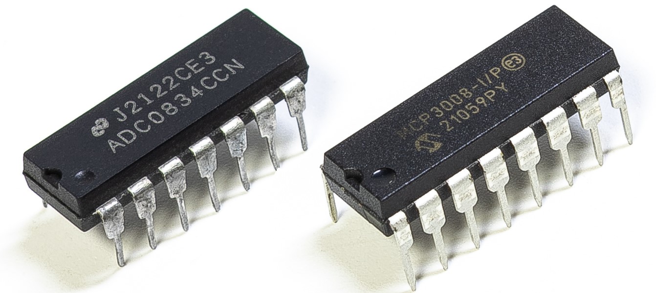
Depending on your kit version, please identify whether you have ADC0834 or MCP3008 and proceed with the matching section.
Introduction
In this project, we will make a battery indicator device that can visually display the battery level on the LED Bargraph.
Warning
Do not use battery components that exceed 3.3V to avoid overloading, which may damage the chip or Raspberry Pi.
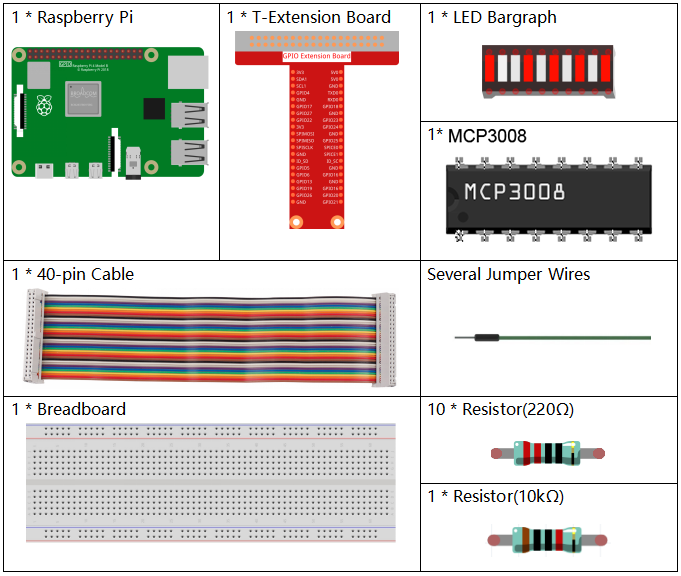
Required Components
In this project, we need the following components.
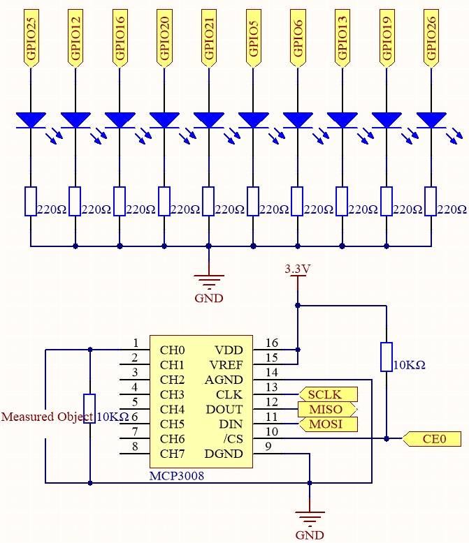
Schematic Diagram
T-Board Name |
physical |
wiringPi |
BCM |
SPICE0 |
Pin 24 |
10 |
8 |
SPIMOSI |
Pin 19 |
12 |
10 |
SPIMISO |
Pin 21 |
13 |
9 |
SPISCLK |
Pin 23 |
14 |
11 |
GPIO25 |
Pin 22 |
6 |
25 |
GPIO12 |
Pin 32 |
26 |
12 |
GPIO16 |
Pin 36 |
27 |
16 |
GPIO20 |
Pin 38 |
28 |
20 |
GPIO21 |
Pin 40 |
29 |
21 |
GPIO5 |
Pin 29 |
21 |
5 |
GPIO6 |
Pin 31 |
22 |
6 |
GPIO13 |
Pin 33 |
23 |
13 |
GPIO19 |
Pin 35 |
24 |
19 |
GPIO26 |
Pin 37 |
25 |
26 |
Experimental Procedures
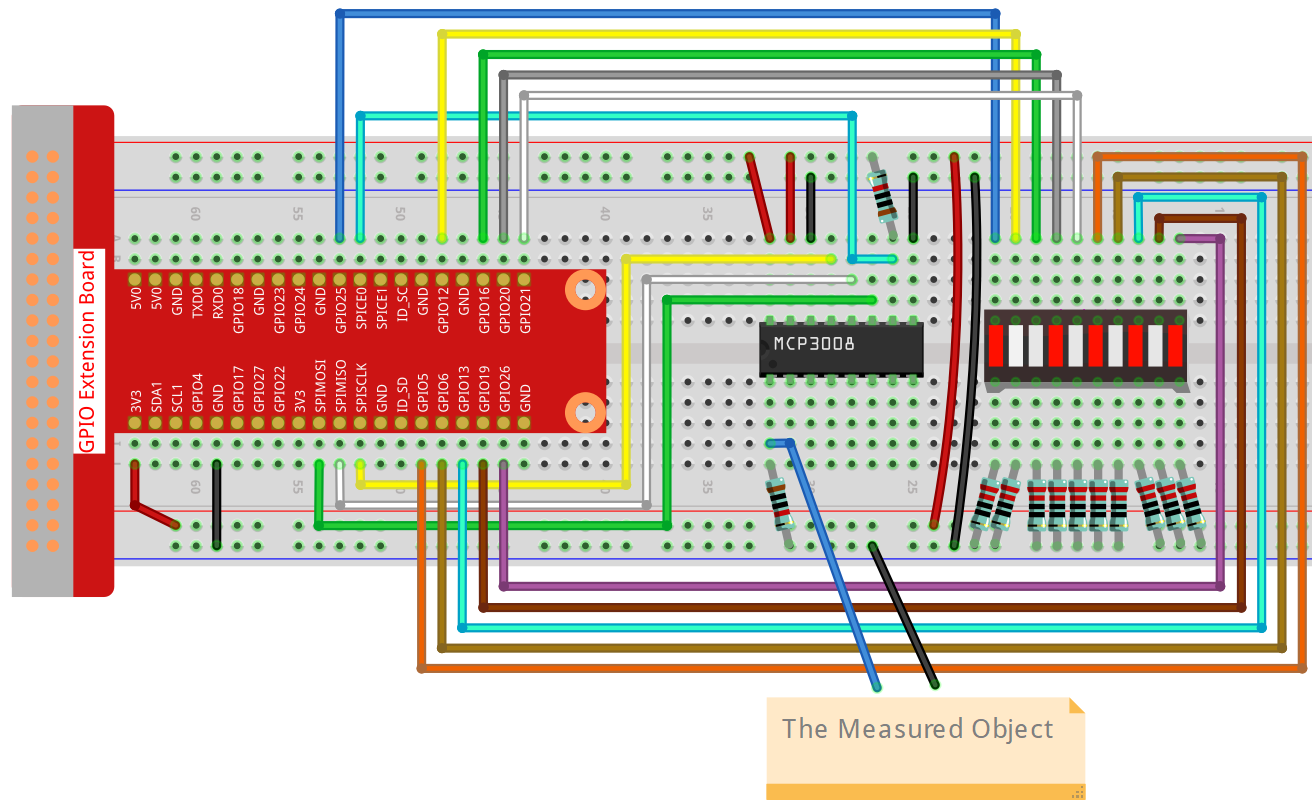
Step 1: Build the circuit.
For C Language Users
Step 2: Go to the folder of the code.
cd ~/davinci-kit-for-raspberry-pi/c/3.1.5-2/
Step 3: Compile the code.
gcc 3.1.5_BatteryIndicator.c -lwiringPi
Step 4: Run the executable file.
sudo ./a.out
After the program runs, give the 3rd pin of MCP3008 and the GND a lead-out wire separately and then lead them to the two poles of a battery separately. You can see the corresponding LED on the LED Bargraph is lit up to display the power level (measuring range: 0-5V).
Note
If it does not work after running, or there is an error prompt: "wiringPi.h: No such file or directory", please refer to Install and Check the WiringPi.
Code
#include <wiringPi.h>
#include <wiringPiSPI.h>
#include <stdio.h>

#define SPI_CHANNEL 0
#define SPI_SPEED   1000000  // 1MHz
#define VREF        3.3

int pins[10] = {6, 26, 27, 28, 29, 21, 22, 23, 24, 25};

int read_ADC(int channel)
{
    if (channel < 0 || channel > 7) return -1;

    unsigned char buffer[3];
    buffer[0] = 1;  // Start bit
    buffer[1] = (8 + channel) << 4;  // Single-ended mode
    buffer[2] = 0;

    wiringPiSPIDataRW(SPI_CHANNEL, buffer, 3);

    int value = ((buffer[1] & 3) << 8) | buffer[2];
    return value;
}

void LedBarGraph(int value) {
    for (int i = 0; i < 10; i++) {
        if (i < value)
        digitalWrite(pins[i], HIGH);
    else
        digitalWrite(pins[i],LOW);
    }
}

int main(void)
{
    if (wiringPiSetup() == -1) {
        printf("setup wiringPi failed!\n");
        return 1;
    }

    if (wiringPiSPISetup(SPI_CHANNEL, SPI_SPEED) == -1) {
        printf("SPI setup failed!\n");
        return 1;
    }

    for (int i = 0; i < 10; i++) {
        pinMode(pins[i], OUTPUT);
        digitalWrite(pins[i], HIGH);
    }

    while (1) {
        int analogVal = read_ADC(0);  // MCP3008 CH0
        if (analogVal < 0) continue;


        float voltage = analogVal * VREF / 1023.0;
        int level = analogVal * 10 / 1024;
        if (level > 10) level = 10;

        LedBarGraph(level);

        printf("ADC Value: %d\tVoltage: %.2f V\tLevel: %d\n", analogVal, voltage, level);

        delay(200);
    }

    return 0;
}
Code Explanation
int read_ADC(int channel)
{
    if (channel < 0 || channel > 7) return -1;

    unsigned char buffer[3];
    buffer[0] = 1;  // Start bit
    buffer[1] = (8 + channel) << 4;  // Single-ended mode, CH0~CH7
    buffer[2] = 0;

    wiringPiSPIDataRW(SPI_CHANNEL, buffer, 3);

    int value = ((buffer[1] & 3) << 8) | buffer[2];  // Combine 10-bit result
    return value;
}
This function reads analog values from the MCP3008 ADC chip using SPI.
The channel parameter selects one of the 8 analog inputs (CH0–CH7).
The MCP3008 returns a 10-bit digital value between 0 and 1023 representing the analog voltage.
void LedBarGraph(int value) {
    for (int i = 0; i < 10; i++) {
        if (i < value)
            digitalWrite(pins[i], HIGH);  // Turn on LED (assumes active HIGH wiring)
        else
            digitalWrite(pins[i], LOW);   // Turn off LED
    }
}
This function controls a 10-LED bar graph display. Each LED represents 1/10th of the voltage range. LEDs are turned on in order up to the specified level.
Note: This version assumes LED anodes are connected to GPIOs and cathodes to GND (i.e. active HIGH).
int main(void)
{
    if (wiringPiSetup() == -1) {
        printf("setup wiringPi failed!\n");
        return 1;
    }

    if (wiringPiSPISetup(SPI_CHANNEL, SPI_SPEED) == -1) {
        printf("SPI setup failed!\n");
        return 1;
    }

    for (int i = 0; i < 10; i++) {
        pinMode(pins[i], OUTPUT);
        digitalWrite(pins[i], HIGH);  // Initialize all LEDs to ON
    }

    while (1) {
        int analogVal = read_ADC(0);  // Read voltage on CH0
        if (analogVal < 0) continue;

        float voltage = analogVal * VREF / 1023.0;
        int level = analogVal * 10 / 1024;  // Map to 0–10 levels
        if (level > 10) level = 10;

        LedBarGraph(level);  // Display level on LEDs

        printf("ADC Value: %d\tVoltage: %.2f V\tLevel: %d\n", analogVal, voltage, level);

        delay(200);  // Update rate: 5 Hz
    }

    return 0;
}
Main program logic:
Initializes wiringPi and SPI communication.
Sets GPIO pins as outputs for controlling the 10-LED bar.
Continuously reads analog voltage via MCP3008 (CH0).
Converts the reading to a voltage using
VREF = 3.3V.Scales voltage to a 0–10 level bar graph and lights up LEDs.
Displays the raw ADC value, voltage (in volts), and LED level via serial console.
This acts as a visual battery level indicator or analog voltmeter.
For Python Language Users
Step 2: Set up the SPI interface and install the spidev library (see SPI Configuration for detailed instructions). If you have already completed these steps, you can skip this.
Step 3: Go to the folder of the code.
cd ~/davinci-kit-for-raspberry-pi/python
Step 4: Run the executable file.
sudo python3 3.1.5-2_BatteryIndicator.py
After the program runs, give the 3rd pin of ADC0834 and the GND a lead-out wire separately and then lead them to the two poles of a battery separately. You can see the corresponding LED on the LED Bargraph is lit up to display the power level (measuring range: 0-5V).
Warning
If there is an error prompt RuntimeError: Cannot determine SOC peripheral base address, please refer to If gpiozero doesn’t work.
Code
Note
You can Modify/Reset/Copy/Run/Stop the code below. But before that, you need to go to source code path like davinci-kit-for-raspberry-pi/python. After modifying the code, you can run it directly to see the effect.
#!/usr/bin/env python3

import RPi.GPIO as GPIO
import spidev
import time

# GPIO pins connected to 10 LEDs, ordered from left to right
led_pins = [25, 12, 16, 20, 21, 5, 6, 13, 19, 26]  # BCM numbering

# GPIO setup
GPIO.setmode(GPIO.BCM)
for pin in led_pins:
    GPIO.setup(pin, GPIO.OUT)
    GPIO.output(pin, GPIO.LOW)

# Initialize SPI
spi = spidev.SpiDev()
spi.open(0, 0)  # Bus 0, CE0
spi.max_speed_hz = 1000000  # 1 MHz

# Read value from MCP3008 channel
def read_adc(channel):
    if channel < 0 or channel > 7:
        return -1
    r = spi.xfer2([1, (8 + channel) << 4, 0])
    value = ((r[1] & 0x03) << 8) | r[2]
    return value

# Light up LED bar graph according to value
def led_bar_graph(level):
    for i, pin in enumerate(led_pins):
        if i < level:
            GPIO.output(pin, GPIO.HIGH)
        else:
            GPIO.output(pin, GPIO.LOW)

# Main loop
try:
    while True:
        analog_val = read_adc(0)  # Read from MCP3008 channel 0
        level = int(analog_val * 10 / 1023)
        led_bar_graph(level)
        print(f"ADC: {analog_val}, Level: {level}")
        time.sleep(0.2)

except KeyboardInterrupt:
    pass

finally:
    for pin in led_pins:
        GPIO.output(pin, GPIO.LOW)
    GPIO.cleanup()
    spi.close()
Code Explanation
This program reads analog voltage from an MCP3008 ADC and displays the result on a 10-LED bar graph using a Raspberry Pi (BCM pin layout).
Import Modules
RPi.GPIOcontrols the GPIO pins on Raspberry Pi.spidevcommunicates with MCP3008 via SPI.timeprovides delay/sleep functionality.
#!/usr/bin/env python3

import RPi.GPIO as GPIO
import spidev
import time
GPIO LED Setup
A list of 10 GPIO pins is defined for LED control. These pins are configured as output and initialized to LOW (off).
# GPIO pins connected to 10 LEDs, ordered from left to right
led_pins = [25, 12, 16, 20, 21, 5, 6, 13, 19, 26]  # BCM numbering

GPIO.setmode(GPIO.BCM)
for pin in led_pins:
    GPIO.setup(pin, GPIO.OUT)
    GPIO.output(pin, GPIO.LOW)
SPI Initialization
Initializes SPI bus 0 and chip enable 0 (CE0) to communicate with MCP3008. The communication speed is set to 1 MHz.
spi = spidev.SpiDev()
spi.open(0, 0)  # Bus 0, CE0
spi.max_speed_hz = 1000000  # 1 MHz
ADC Read Function
Reads an analog value from a specified MCP3008 channel (0–7). The function sends a 3-byte SPI command and decodes the 10-bit result.
def read_adc(channel):
    if channel < 0 or channel > 7:
        return -1
    r = spi.xfer2([1, (8 + channel) << 4, 0])
    value = ((r[1] & 0x03) << 8) | r[2]
    return value
LED Bar Graph Function
Lights up LEDs based on the analog level. If the level is 7, the first 7 LEDs will be ON and the rest OFF.
def led_bar_graph(level):
    for i, pin in enumerate(led_pins):
        if i < level:
            GPIO.output(pin, GPIO.HIGH)
        else:
            GPIO.output(pin, GPIO.LOW)
Main Loop
Continuously reads analog input from channel 0, scales the result to a value from 0 to 10, and updates the LED display accordingly. Prints ADC and level values for monitoring.
try:
    while True:
        analog_val = read_adc(0)
        level = int(analog_val * 10 / 1023)
        led_bar_graph(level)
        print(f"ADC: {analog_val}, Level: {level}")
        time.sleep(0.2)
Cleanup on Exit
When
Ctrl+Cis pressed, the program turns off all LEDs, cleans up GPIO state, and closes the SPI interface.except KeyboardInterrupt: pass finally: for pin in led_pins: GPIO.output(pin, GPIO.LOW) GPIO.cleanup() spi.close()