Tilt LED 2.0
Note
🌟 Welcome to the SunFounder Facebook Community! Whether you’re into Raspberry Pi, Arduino, or ESP32, you’ll find inspiration, help ideas here.
✅ Be the first to get free learning resources.
✅ Stay updated on new products & exclusive giveaways.
✅ Share your creations and get real feedback.
Kit purchase
Looking for parts? Check out our all-in-one kits below — packed with components, beginner-friendly guides, and tons of fun.

Name |
Includes ESP32 board |
PURCHASE LINK |
|---|---|---|
ESP32 Ultimate Starter Kit |
ESP32 WROOM 32E + |
|
Universal Maker Sensor Kit |
Course Introduction
This project controls an array of LEDs based on the tilt angle detected by an MPU6050 sensor.
The LEDs illuminate in response to X-axis tilt, visually indicating the board’s orientation.
Tilt angles are continuously calculated from acceleration data provided by the MPU6050, and corresponding LEDs activate according to predefined angle thresholds.
Note
If this is your first time working with an ESP32 project, we recommend downloading and reviewing the basic materials first.
Required Components
In this project, we need the following components:
SN |
COMPONENT INTRODUCTION |
QUANTITY |
PURCHASE LINK |
|---|---|---|---|
1 |
Arduino Nano ESP32 |
1 |
|
2 |
USB Type-C cable |
1 |
|
3 |
Breadboard |
1 |
|
4 |
Wires |
Several |
|
5 |
1kΩ resistor |
Several |
|
6 |
LED |
Several |
|
7 |
MPU6050 Module |
1 |
Wiring
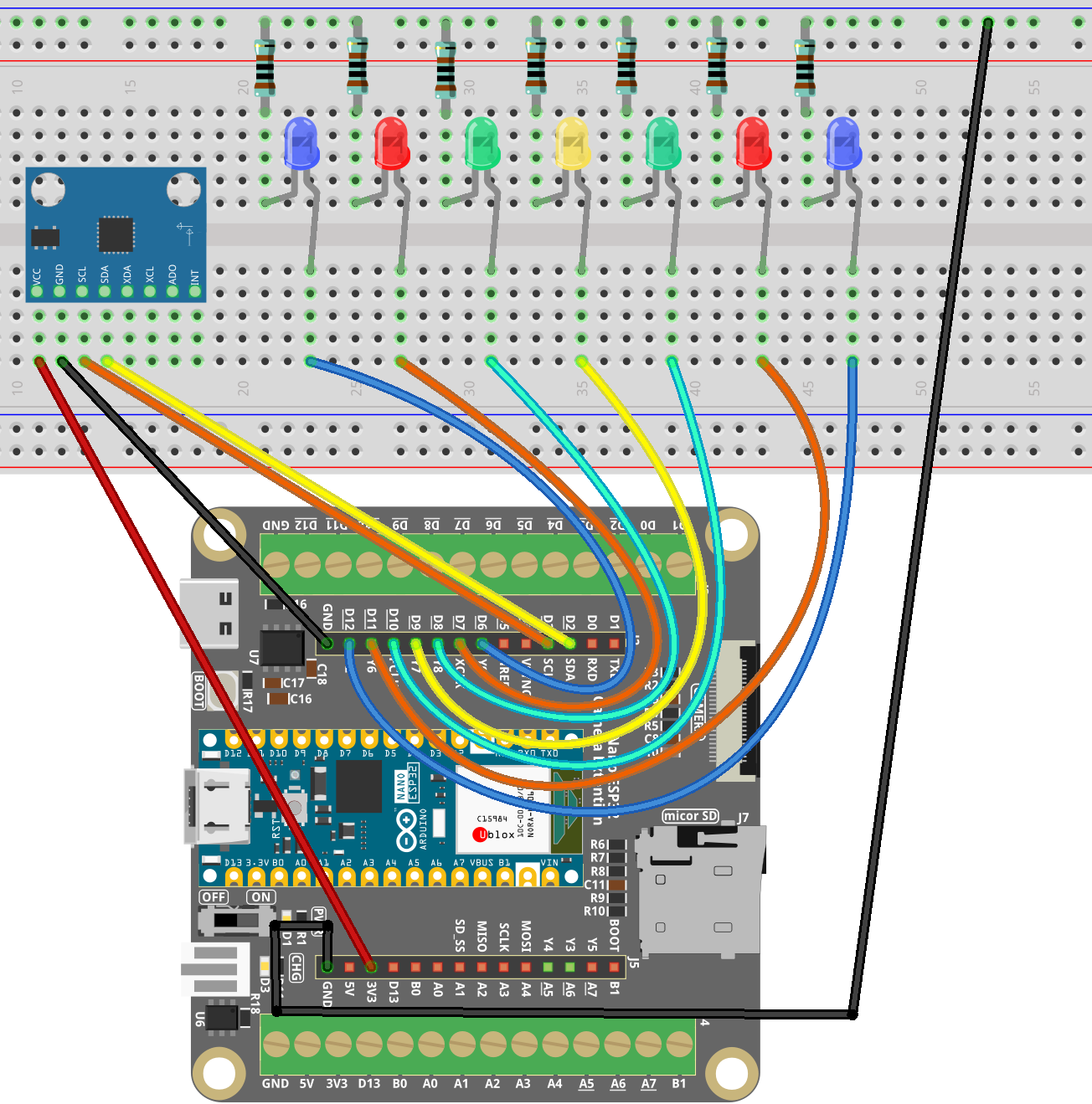
Common Connections:
LED
Connect the LEDs cathode to a 1kΩ resistor then to the negative power bus on the breadboard, and the LEDs anode to D6 to D12 on the ESP32.
MPU6050
SDA: Connect to D2 on the ESP32.
SCL: Connect to D3 on the ESP32.
GND: Connect to breadboard’s negative power bus.
VCC: Connect to breadboard’s red power bus.
Writing the Code
Note
You can copy this code into Arduino IDE.
To install the library, use the Arduino Library Manager and search for MPU6050 and install it.
Don’t forget to select the board(Arduino Nano ESP32) and the correct port before clicking the Upload button.
#include <Wire.h>
#include <MPU6050.h>

MPU6050 mpu;

// LED pins (you have verified these work)
// Pin -> LED -> Resistor -> GND (HIGH = ON)
const int ledPins[] = {12, 11, 10, 9, 8, 7, 6};
const int ledCount = sizeof(ledPins) / sizeof(ledPins[0]);

// 6 boundaries -> 7 LED regions
const float thresholds[] = {-30, -15, -5, 5, 15, 30};

// LED helpers
void ledWrite(int pin, bool on) {
  digitalWrite(pin, on ? HIGH : LOW);
}

void allLedsOff() {
  for (int i = 0; i < ledCount; i++) ledWrite(ledPins[i], false);
}

void allLedsOn() {
  for (int i = 0; i < ledCount; i++) ledWrite(ledPins[i], true);
}

// LED self-test to confirm wiring
void ledSelfTest() {
  allLedsOff();

  for (int i = 0; i < ledCount; i++) {
    ledWrite(ledPins[i], true);
    delay(200);
    ledWrite(ledPins[i], false);
  }

  allLedsOn();
  delay(400);
  allLedsOff();
  delay(200);
}

// Map angle to LED index
int getLEDIndex(float angleX) {
  const int n = sizeof(thresholds) / sizeof(thresholds[0]);
  for (int i = 0; i < n; i++) {
    if (angleX < thresholds[i]) return i;
  }
  return ledCount - 1;
}

void updateLEDs(float angleX) {
  allLedsOff();
  int idx = getLEDIndex(angleX);
  if (idx >= 0 && idx < ledCount) {
    ledWrite(ledPins[idx], true);
  }
}

void setup() {
  Serial.begin(115200);
  delay(200);

  // LED setup
  for (int i = 0; i < ledCount; i++) {
    pinMode(ledPins[i], OUTPUT);
    ledWrite(ledPins[i], false);
  }

  Serial.println("LED self-test start...");
  ledSelfTest();
  Serial.println("LED self-test done.");

  // ---- I2C init (IMPORTANT CHANGE) ----
  // MPU6050 SDA -> D2
  // MPU6050 SCL -> D3
  Wire.begin(D2, D3);

  // MPU6050 init
  Serial.println("Init MPU6050...");
  mpu.initialize();

  if (!mpu.testConnection()) {
    Serial.println("MPU6050 connection failed. Blinking all LEDs.");
    while (true) {
      allLedsOn();
      delay(300);
      allLedsOff();
      delay(300);
    }
  }

  Serial.println("MPU6050 connected.");
}

void loop() {
  int16_t ax, ay, az;
  mpu.getAcceleration(&ax, &ay, &az);

  // Calculate tilt angle around X axis
  float angleX = atan2((float)ay, (float)az) * 180.0f / PI;

  Serial.print("angleX=");
  Serial.println(angleX);

  updateLEDs(angleX);
  delay(100);
}