Stair Light
Note
🌟 Welcome to the SunFounder Facebook Community! Whether you’re into Raspberry Pi, Arduino, or ESP32, you’ll find inspiration and help here.
✅ Be the first to get free learning resources.
✅ Stay updated on new products & exclusive giveaways.
✅ Share your creations and get real feedback.
Kit purchase
Looking for parts? Check out our all-in-one kits below — packed with components, beginner-friendly guides, and tons of fun.
Name |
Includes ESP32 board |
PURCHASE LINK |
|---|---|---|
ESP32 Ultimate Starter Kit |
ESP32 WROOM 32E + |
|
Universal Maker Sensor Kit |
Course Introduction
In this lesson, you’ll use a PIR motion sensor, an LED, and a button with the Arduino Nano ESP32 to build a smart lighting system with three operating modes.
The system can automatically turn on the LED when motion is detected, keep it always on, or keep it always off. A single button toggles between these modes, and the LED behavior updates accordingly.
Note
If this is your first time working with an ESP32 project, we recommend downloading and reviewing the basic materials first.
Required Components
In this project, we need the following components:
SN |
COMPONENT INTRODUCTION |
QUANTITY |
PURCHASE LINK |
|---|---|---|---|
1 |
Arduino Nano ESP32 |
1 |
|
2 |
USB Type-C cable |
1 |
|
3 |
Breadboard |
1 |
|
4 |
Wires |
Several |
|
5 |
PIR Motion Sensor |
1 |
|
6 |
Button |
1 |
|
7 |
LED |
1 |
|
8 |
1kΩ resistor |
1 |
Wiring
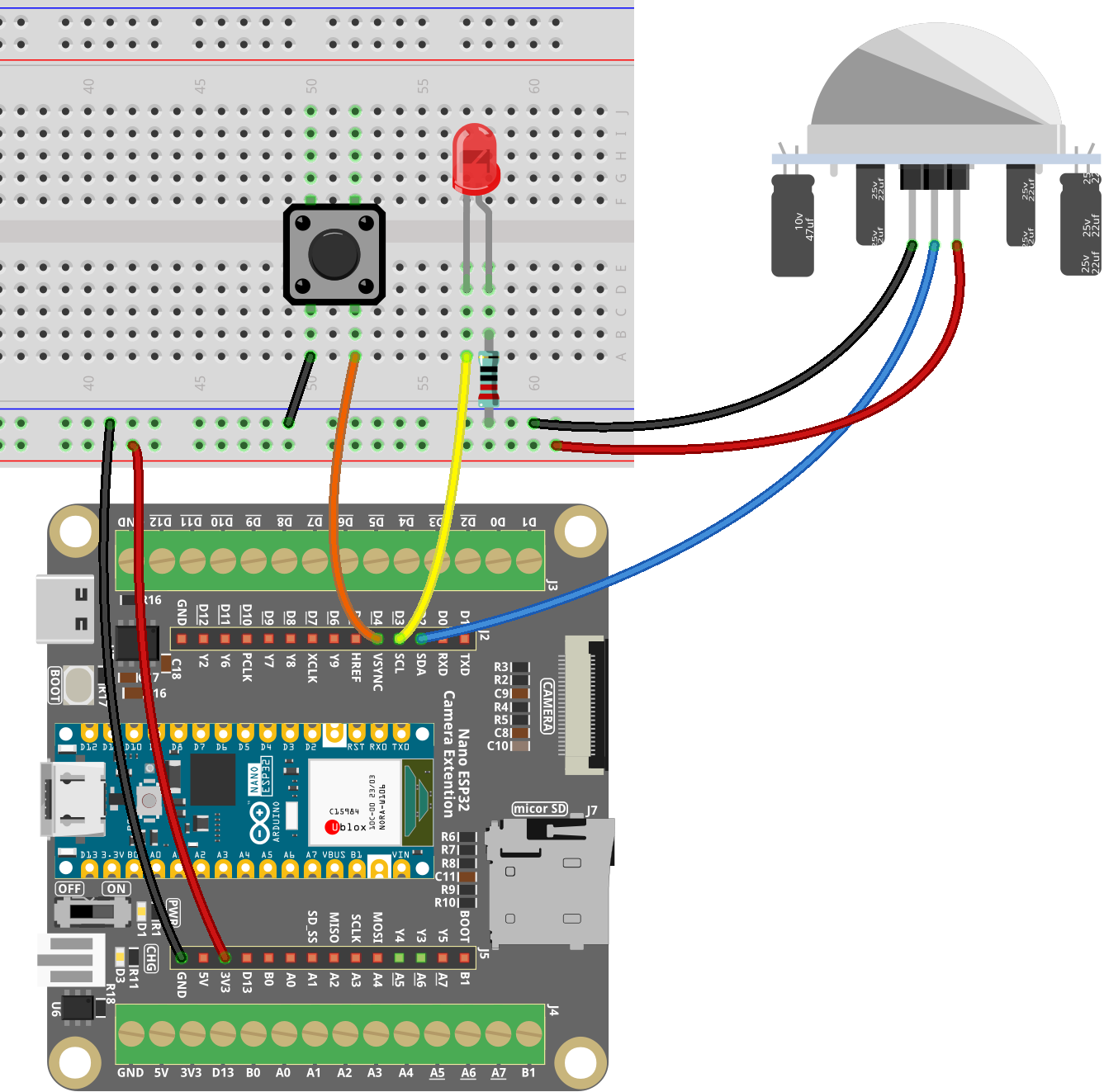
Common Connections:
LED
Connect the LED cathode to the to a 220Ω resistor, then to negative power bus on the breadboard, anode to D3 on the ESP32.
PIR
+: Connect to D2 on the ESP32.
-: Connect to breadboard’s negative power bus.
Button
Connect to the breadboard’s negative power bus, and the other end to D4 on the ESP32 board.
Writing the Code
Note
You can copy this code into Arduino IDE.
Don’t forget to select the board(Arduino Nano ESP32) and the correct port before clicking the Upload button.
// Arduino Nano ESP32 version (ESP32-based)
// Uses D2/D3/D4 to match the board's Arduino pin mapping.

const int PIR_PIN = D2;       // PIR motion sensor signal pin
const int LED_PIN = D3;       // External LED pin
const int BUTTON_PIN = D4;    // Button pin (active LOW with internal pull-up)

int mode = 0;                 // 0 = Auto, 1 = Always ON, 2 = Always OFF
bool lastButtonState = HIGH;
unsigned long lastMotionTime = 0;
const unsigned long LIGHT_DELAY = 3000; // 3s delay

void setup() {
  // PIR output can float on some sensors, pull-down can help stability.
  // If your PIR module already has a stable output, INPUT is also fine.
  pinMode(PIR_PIN, INPUT);                 // or INPUT_PULLDOWN if needed
  pinMode(LED_PIN, OUTPUT);
  pinMode(BUTTON_PIN, INPUT_PULLUP);       // Internal pull-up, button to GND

  digitalWrite(LED_PIN, LOW);

  Serial.begin(115200);
  delay(300); // Small delay for USB serial to get ready on some systems
  Serial.println("Mode 0: Auto, Mode 1: Always ON, Mode 2: Always OFF");
}

void loop() {
  // ---- Button detection (toggle between modes) ----
  bool buttonState = digitalRead(BUTTON_PIN);
  if (buttonState == LOW && lastButtonState == HIGH) {
    mode = (mode + 1) % 3;  // Cycle through 0->1->2->0
    Serial.print("Mode: ");
    if (mode == 0) Serial.println("Auto");
    else if (mode == 1) Serial.println("Always ON");
    else Serial.println("Always OFF");
    delay(200); // Debounce
  }
  lastButtonState = buttonState;

  // ---- Mode control ----
  if (mode == 1) {
    // Always ON
    digitalWrite(LED_PIN, HIGH);
  } else if (mode == 2) {
    // Always OFF
    digitalWrite(LED_PIN, LOW);
  } else {
    // Auto mode (PIR control)
    int motion = digitalRead(PIR_PIN);
    if (motion == HIGH) {
      digitalWrite(LED_PIN, HIGH);
      lastMotionTime = millis(); // Record time when motion detected
    } else if (millis() - lastMotionTime > LIGHT_DELAY) {
      digitalWrite(LED_PIN, LOW);
    }
  }
}