Speed Meter
Note
🌟 Welcome to the SunFounder Facebook Community! Whether you’re into Raspberry Pi, Arduino, or ESP32, you’ll find inspiration, help ideas here.
✅ Be the first to get free learning resources.
✅ Stay updated on new products & exclusive giveaways.
✅ Share your creations and get real feedback.
Kit purchase
Looking for parts? Check out our all-in-one kits below — packed with components, beginner-friendly guides, and tons of fun.
Name |
Includes ESP32 board |
PURCHASE LINK |
|---|---|---|
ESP32 Ultimate Starter Kit |
ESP32 WROOM 32E + |
|
Universal Maker Sensor Kit |
Course Introduction
In this lesson, you’ll learn how to use an L9110 Motor Driver Module, a TT motor, and an OLED display with the Arduino Nano ESP32 to build a simple Motor Speed Control system.
A button press cycles through multiple speed levels, and the motor speed is displayed on the OLED as both a numeric RPM value and a bar graph.
Note
If this is your first time working with an Arduino project, we recommend downloading and reviewing the basic materials first.
Required Components
In this project, we need the following components:
SN |
COMPONENT INTRODUCTION |
QUANTITY |
PURCHASE LINK |
|---|---|---|---|
1 |
Arduino Nano ESP32 |
1 |
|
2 |
USB Cable |
1 |
|
3 |
Breadboard |
1 |
|
4 |
Wires |
Several |
|
5 |
L9110 Motor Driver Module |
1 |
|
6 |
OLED Display Module |
1 |
|
7 |
TT Motor |
1 |
|
8 |
Button |
1 |
Wiring
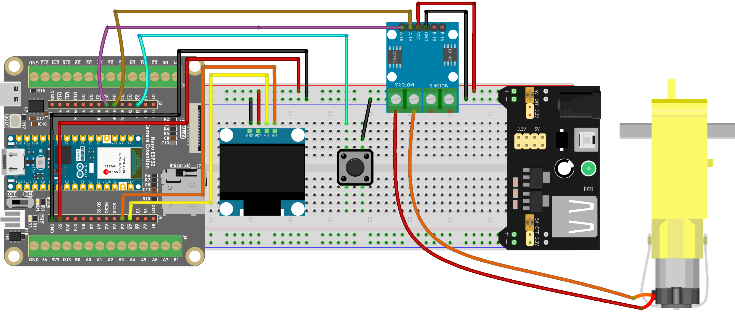
Common Connections:
OLED Display Module
SDA: Connect to A4 on the ESP32.
SCK: Connect to A5 on the ESP32.
GND: Connect to breadboard’s negative power bus.
VCC: Connect to breadboard’s red power bus.
Button
Connect to breadboard’s negative power bus.
Connect to D2 on the ESP32.
TT Motor
Connect to MOTOR A on the L9110 Motor Driver Module.
L9110 Motor Driver Module
GND: Connect to breadboard’s negative power bus.
VCC: Connect to breadboard’s red power bus.
A-1B: Connect to D5 on the Arduino.
A-1A: Connect to D6 on the Arduino.
Writing the Code
Note
You can copy this code into Arduino IDE.
To install the library, use the Arduino Library Manager and search for Adafruit SSD1306 and Adafruit GFX and install it.
Don’t forget to select the board(Arduino UNO R4) and the correct port before clicking the Upload button.
#include <Wire.h>
#include <Adafruit_GFX.h>
#include <Adafruit_SSD1306.h>

// -------------------- OLED Settings --------------------
#define SCREEN_WIDTH 128
#define SCREEN_HEIGHT 64
#define OLED_RESET    -1
#define OLED_ADDR     0x3C

Adafruit_SSD1306 display(SCREEN_WIDTH, SCREEN_HEIGHT, &Wire, OLED_RESET);

// -------------------- Motor Pins (L9110) --------------------
#define MOTOR_PIN1 5
#define MOTOR_PIN2 6

// -------------------- Button Pin --------------------
#define BUTTON_PIN 2

// -------------------- Motor Speed Levels --------------------
// PWM duty values (0..255)
int speedLevels[5] = {0, 190, 200, 230, 255};
int currentLevel = 0;

// -------------------- Button Debounce --------------------
bool lastButtonState = HIGH;
unsigned long lastDebounceTime = 0;
const unsigned long debounceDelay = 200;

// -------------------- ESP32 PWM (LEDC) Settings --------------------
// New ESP32 core supports ledcAttach(pin, freq, resolutionBits)
const uint32_t PWM_FREQ = 20000;   // 20kHz
const uint8_t  PWM_RES  = 8;       // 8-bit => duty 0..255

// -------------------- Helper: set motor duty --------------------
void setMotorPWM(int duty1, int duty2) {
  // Clamp to 0..255
  if (duty1 < 0) duty1 = 0;
  if (duty1 > 255) duty1 = 255;
  if (duty2 < 0) duty2 = 0;
  if (duty2 > 255) duty2 = 255;

  // Write PWM duty by pin (ESP32 new API)
  ledcWrite(MOTOR_PIN1, duty1);
  ledcWrite(MOTOR_PIN2, duty2);
}

void setup() {
  pinMode(BUTTON_PIN, INPUT_PULLUP);

  // -------------------- Setup ESP32 PWM --------------------
  // Attach PWM to both motor pins
  ledcAttach(MOTOR_PIN1, PWM_FREQ, PWM_RES);
  ledcAttach(MOTOR_PIN2, PWM_FREQ, PWM_RES);

  // Motor stop at boot
  setMotorPWM(0, 0);

  // -------------------- Initialize OLED --------------------
  if (!display.begin(SSD1306_SWITCHCAPVCC, OLED_ADDR)) {
    while (true) { delay(1000); } // Stop if OLED not found
  }
  display.clearDisplay();
  display.display();
}

void loop() {
  handleButton();
  updateMotor();
  drawSpeed();
  delay(50);
}

void handleButton() {
  bool buttonState = digitalRead(BUTTON_PIN);

  // Detect falling edge with debounce
  if (buttonState == LOW && lastButtonState == HIGH &&
      (millis() - lastDebounceTime) > debounceDelay) {

    currentLevel++;
    if (currentLevel > 4) currentLevel = 0; // Loop back to stop
    lastDebounceTime = millis();
  }

  lastButtonState = buttonState;
}

void updateMotor() {
  int speed = speedLevels[currentLevel];

  // Forward: IN1 = PWM, IN2 = 0
  // Stop: both 0
  if (speed == 0) {
    setMotorPWM(0, 0);
  } else {
    setMotorPWM(speed, 0);
  }
}

void drawSpeed() {
  int pwm = speedLevels[currentLevel];

  // Approximate RPM display (just a rough mapping)
  float rpm = (pwm / 255.0f) * 200.0f;

  // Bar length (max 100px)
  int barLength = map(pwm, 0, 255, 0, 100);

  display.clearDisplay();

  // --- Display numeric speed (big font) ---
  display.setTextSize(2);
  display.setTextColor(SSD1306_WHITE);
  display.setCursor(0, 0);
  display.print("RPM");

  display.setCursor(0, 20);
  display.print((int)rpm);

  // --- Draw bar graph ---
  display.drawRect(10, 50, 100, 10, SSD1306_WHITE);
  display.fillRect(10, 50, barLength, 10, SSD1306_WHITE);

  display.display();
}