RGB Controll
Note
🌟 Welcome to the SunFounder Facebook Community! Whether you’re into Raspberry Pi, Arduino, or ESP32, you’ll find inspiration, help ideas here.
✅ Be the first to get free learning resources.
✅ Stay updated on new products & exclusive giveaways.
✅ Share your creations and get real feedback.
Kit purchase
Looking for parts? Check out our all-in-one kits below — packed with components, beginner-friendly guides, and tons of fun.

Name |
Includes ESP32 board |
PURCHASE LINK |
|---|---|---|
ESP32 Ultimate Starter Kit |
ESP32 WROOM 32E + |
|
Universal Maker Sensor Kit |
Course Introduction
In this lesson, you’ll learn how to use a potentiometer with the Arduino Nano ESP32 to control an RGB LED.
As you turn the knob, the LED color smoothly transitions through red, yellow, green, and blue, creating a dynamic color blending effect.
Note
If this is your first time working with an ESP32 project, we recommend downloading and reviewing the basic materials first.
Required Components
In this project, we need the following components:
SN |
COMPONENT INTRODUCTION |
QUANTITY |
PURCHASE LINK |
|---|---|---|---|
1 |
Arduino Nano ESP32 |
1 |
|
2 |
USB Type-C cable |
1 |
|
3 |
Breadboard |
1 |
|
4 |
Wires |
Several |
|
5 |
Potentiometer |
1 |
|
6 |
RGB LED |
1 |
Wiring
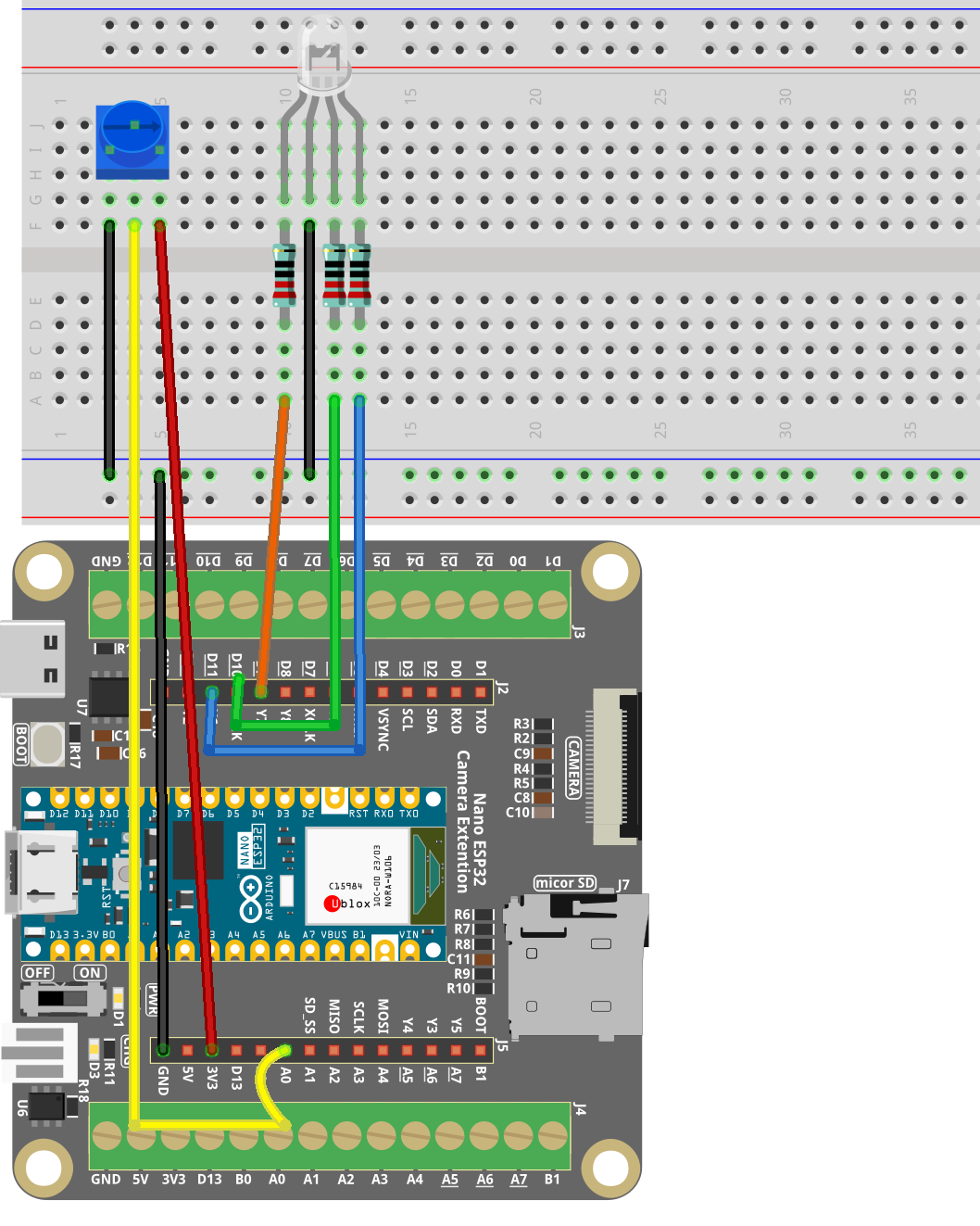
Common Connections:
RGB LED
R: Connect to D9 on the ESP32.
Y: Connect to D10 on the ESP32.
G: Connect to D11 on the ESP32.
GND: Connect to breadboard’s negative power bus.
Potentiometer
OUT: Connect to A0 on the ESP32.
GND: Connect to breadboard’s negative power bus.
VCC: Connect to 3.3V on the ESP32 Extension Board.
Writing the Code
Note
You can copy this code into Arduino IDE.
Don’t forget to select the board(Arduino Nano ESP32) and the correct port before clicking the Upload button.
/*
  Arduino Nano ESP32 (ESP32-S3)
  RGB LED color blending with potentiometer (LEDC PWM)
*/

// RGB LED pins (use Dx labels)
const int redPin   = D9;
const int greenPin = D10;
const int bluePin  = D11;

// Potentiometer pin (ADC)
const int potPin = A0;

// PWM settings
const int PWM_FREQ = 5000;     // 5 kHz
const int PWM_RES  = 8;        // 8-bit resolution (0~255)

void setup() {
  Serial.begin(115200);
  delay(200);

  // Attach PWM to pins (Arduino-ESP32 3.x style)
  ledcAttach(redPin,   PWM_FREQ, PWM_RES);
  ledcAttach(greenPin, PWM_FREQ, PWM_RES);
  ledcAttach(bluePin,  PWM_FREQ, PWM_RES);

  // Optional: Set ADC behavior (not required, but helps stability)
  analogReadResolution(12); // ESP32 ADC default is typically 12-bit (0~4095)
}

void loop() {
  // Read potentiometer value (ESP32 ADC: 0~4095)
  int potValue = analogRead(potPin);
  Serial.println(potValue);

  // Map ADC value to 0~765 for color blending
  int range = map(potValue, 0, 4095, 0, 765);

  int r = 0, g = 0, b = 0;

  // Blend RGB colors based on range
  if (range <= 255) {
    r = 255;
    g = range;
    b = 0;
  } else if (range <= 510) {
    r = 510 - range;
    g = 255;
    b = range - 255;
  } else {
    r = 0;
    g = 765 - range;
    b = 255;
  }

  // Output PWM (inverted for common-anode RGB LED)
  // If you are using common-cathode, remove the "255 -" inversion.
  ledcWrite(redPin,   255 - r);
  ledcWrite(greenPin, 255 - g);
  ledcWrite(bluePin,  255 - b);

  delay(20);
}