Nota
Ciao, benvenuto nella Community di Appassionati di Raspberry Pi & Arduino & ESP32 di SunFounder su Facebook! Approfondisci Raspberry Pi, Arduino ed ESP32 insieme ad altri appassionati.
Perché Unirsi?
Supporto da Esperti: Risolvi problemi post-vendita e sfide tecniche con l’aiuto della nostra community e del nostro team.
Impara e Condividi: Scambia suggerimenti e tutorial per migliorare le tue competenze.
Anteprime Esclusive: Ottieni accesso anticipato agli annunci dei nuovi prodotti e alle anteprime.
Sconti Speciali: Approfitta di sconti esclusivi sui nostri prodotti più recenti.
Promozioni e Giveaway Festivi: Partecipa ai giveaway e alle promozioni festive.
👉 Pronto a esplorare e creare con noi? Clicca [Qui] e unisciti oggi stesso!
7.3 Lampada Sirena di Allarme
Le luci della polizia sono spesso visibili nella vita reale (o nei film). Di solito vengono utilizzate per mantenere il traffico, fungere da dispositivo di avvertimento e come importante strumento di sicurezza per agenti, veicoli di emergenza, camion dei pompieri e veicoli da lavoro. Quando vedi le loro luci o senti il loro suono, devi fare attenzione, significa che tu (o chi ti circonda) potresti essere in pericolo.
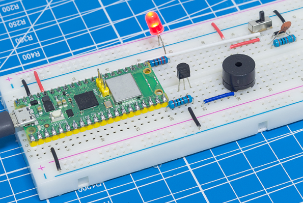
Qui utilizziamo un LED e un buzzer per creare una piccola luce di avvertimento, che viene attivata da un interruttore a slitta.
Componenti Necessari
In questo progetto, abbiamo bisogno dei seguenti componenti.
È sicuramente conveniente acquistare un kit completo, ecco il link:
Nome |
ELEMENTI IN QUESTO KIT |
LINK |
|---|---|---|
Kepler Kit |
450+ |
Puoi anche acquistarli separatamente dai link sottostanti.
SN |
COMPONENTE |
QUANTITÀ |
LINK |
|---|---|---|---|
1 |
1 |
||
2 |
Cavo Micro USB |
1 |
|
3 |
1 |
||
4 |
Diversi |
||
5 |
1 |
||
6 |
1(S8050) |
||
7 |
3(1KΩ, 220Ω, 10KΩ) |
||
8 |
Passive Cicalino |
1 |
|
9 |
1(104) |
||
10 |
1 |
Schema
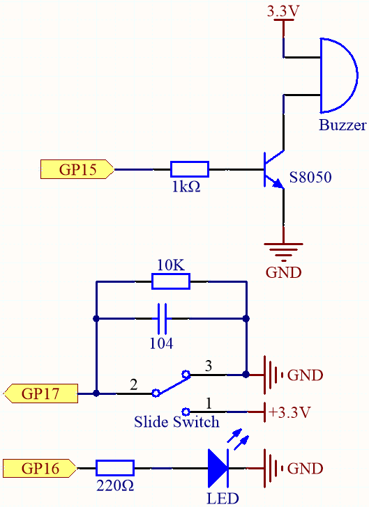
GP17 è collegato al pin centrale dell’interruttore a slitta, insieme a una resistenza da 10K e a un condensatore (filtro) in parallelo al GND, permettendo all’interruttore di uscire un livello alto o basso stabile quando viene spostato a sinistra o a destra.
Appena GP15 è alto, il transistor NPN conduce, facendo suonare il buzzer passivo. Questo buzzer passivo è programmato per aumentare gradualmente la frequenza e produrre un suono di sirena.
Un LED è collegato a GP16 ed è programmato per cambiare periodicamente la sua luminosità per simulare una sirena.
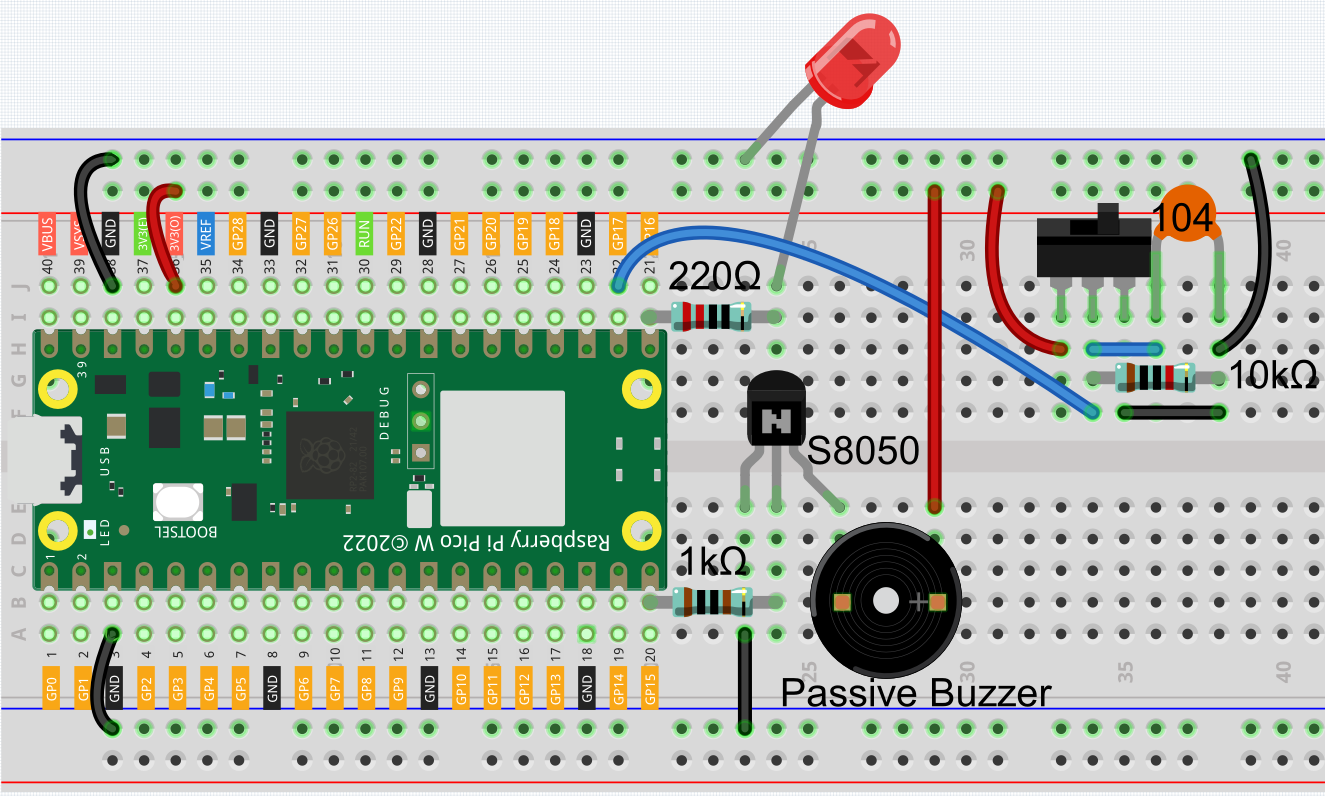
Cablaggio
Codice
Nota
Apri il file
7.3_alarm_siren_lamp.pynel percorsokepler-kit-main/micropythonoppure copia questo codice in Thonny, quindi clicca su «Run Current Script» o semplicemente premi F5 per eseguirlo.Non dimenticare di selezionare l’interprete «MicroPython (Raspberry Pi Pico)» nell’angolo in basso a destra.
Per tutorial dettagliati, fai riferimento a Aprire ed Eseguire Codice Direttamente.
import machine
import time

# Initialize the PWM for the buzzer (on pin 15) and LED (on pin 16)
buzzer = machine.PWM(machine.Pin(15))  # PWM for buzzer
led = machine.PWM(machine.Pin(16))  # PWM for LED
led.freq(1000)  # Set the frequency of the LED PWM to 1kHz

# Initialize the switch (on pin 17) as an input pin
switch = machine.Pin(17, machine.Pin.IN)

# Function to stop the buzzer by setting the duty cycle to 0%
def noTone(pin):
    pin.duty_u16(0)  # Set the PWM duty cycle to 0, stopping the sound

# Function to play a tone on the buzzer with a specified frequency
def tone(pin, frequency):
    pin.freq(frequency)  # Set the frequency for the buzzer
    pin.duty_u16(30000)  # Set duty cycle to around 50% (30000 out of 65535)

# Function to map a value from one range to another
def interval_mapping(x, in_min, in_max, out_min, out_max):
    return (x - in_min) * (out_max - out_min) / (in_max - in_min) + out_min

# Interrupt handler function to toggle the bell_flag when the switch is pressed
def toggle(pin):
    global bell_flag
    bell_flag = not bell_flag  # Toggle the bell_flag value
    print(bell_flag)  # Print the current state of bell_flag for debugging

    # Change the switch interrupt depending on the state of the bell_flag
    if bell_flag:
        # If bell_flag is True, listen for a falling edge (when switch is released)
        switch.irq(trigger=machine.Pin.IRQ_FALLING, handler=toggle)
    else:
        # If bell_flag is False, listen for a rising edge (when switch is pressed)
        switch.irq(trigger=machine.Pin.IRQ_RISING, handler=toggle)

# Initialize bell_flag to False (buzzer and LED off by default)
bell_flag = False

# Set up an interrupt to detect when the switch is pressed (rising edge)
switch.irq(trigger=machine.Pin.IRQ_RISING, handler=toggle)

# Main loop to control the buzzer and LED based on the bell_flag
while True:
    if bell_flag == True:
        # If bell_flag is True, gradually increase the brightness of the LED
        # and change the buzzer frequency to simulate a bell ringing effect
        for i in range(0, 100, 2):  # Loop from 0 to 100 in steps of 2
            led.duty_u16(int(interval_mapping(i, 0, 100, 0, 65535)))  # Map i to LED brightness
            tone(buzzer, int(interval_mapping(i, 0, 100, 130, 800)))  # Map i to buzzer frequency
            time.sleep_ms(10)  # Short delay to create a smooth ramp
    else:
        # If bell_flag is False, stop the buzzer and turn off the LED
        noTone(buzzer)  # Stop the buzzer
        led.duty_u16(0)  # Turn off the LED (set duty cycle to 0)
Una volta eseguito il programma, sposta l’interruttore a slitta a sinistra (il tuo potrebbe essere a destra, a seconda di come è cablato l’interruttore) e il buzzer emetterà un tono di avvertimento progressivo e il LED cambierà di conseguenza la sua luminosità; sposta l’interruttore a slitta a destra e il buzzer e il LED smetteranno di funzionare.