Note
Hello, welcome to the SunFounder Raspberry Pi & Arduino & ESP32 Enthusiasts Community on Facebook! Dive deeper into Raspberry Pi, Arduino, and ESP32 with fellow enthusiasts.
Why Join?
Expert Support: Solve post-sale issues and technical challenges with help from our community and team.
Learn & Share: Exchange tips and tutorials to enhance your skills.
Exclusive Previews: Get early access to new product announcements and sneak peeks.
Special Discounts: Enjoy exclusive discounts on our newest products.
Festive Promotions and Giveaways: Take part in giveaways and holiday promotions.
👉 Ready to explore and create with us? Click [here] and join today!
Lesson 2 Flowing LED Lights
Introduction
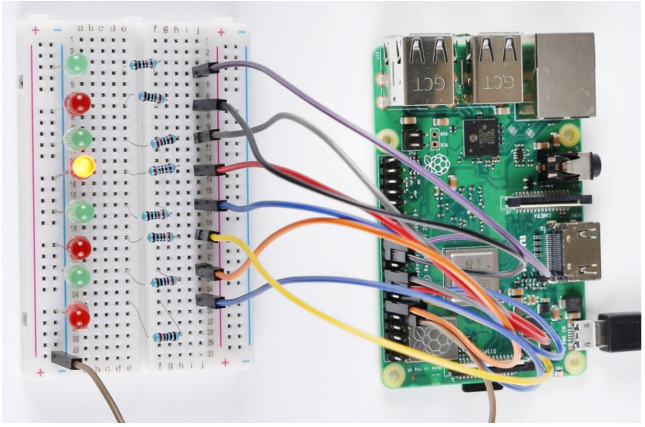
In this lesson, we will learn how to make eight LEDs blink as flowing water based on Raspberry Pi.
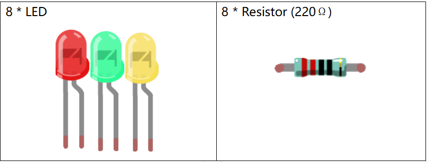
Newly Added Components
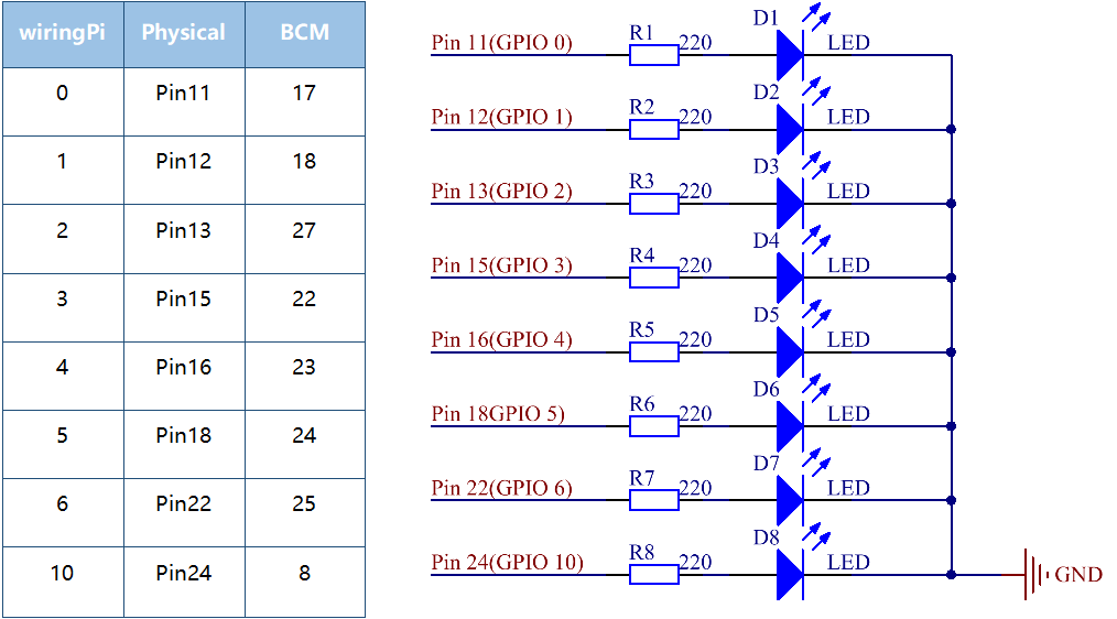
Schematic Diagram
In this experiment, connect 220Ωresistors to the anode (the longer pin of the LED) respectively, then the resistors to Pin 11, 12, 13, 15, 16, 18, 22 and 24 of Raspberry Pi, and connect the cathode (the short pin) of the LEDs to GND. We can see from the schematic diagram that the anode of LED connect to a current-limiting resistor and then to Raspberry Pi. Therefore, to turn on an LED, we need to make pins high level. This process can be realized by programming.
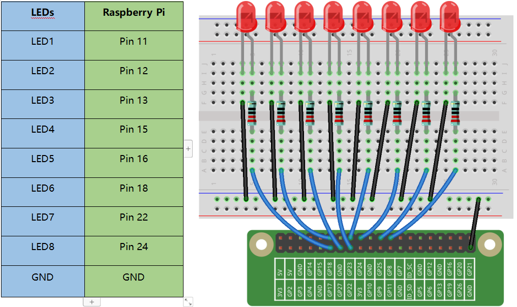
Build the Circuit
For C Language Users:
Command
1. Go to the folder of the code.
cd /home/pi/electronic-kit/for-raspberry-pi/c/Lesson_2_FlowingLedLights
2. Compile the code.
gcc 2_FlowingLedLights.c -lwiringPi
Note
When using the gcc command, if you do not use -o, it will automatically output as a.out.
3. Run the executable file.
sudo ./a.out
Now, you will see these 8 LEDs are lit one by one from left to right, and then one by one from right to left.
Note
If it does not work after running, or there is an error prompt: "wiringPi.h: No such file or directory", please refer to C code is not working?.
Code
#include <wiringPi.h>
#include <stdio.h>

const int LedPin[]={0,1,2,3,4,5,6,10};   //Define 8 LED pin

int main(void)
{
    // When initialize wiring failed, print message to screen
    if(wiringPiSetup() == -1){
        printf("setup wiringPi failed !");
        return 1;
    }

    for(int j=0;j<8;j++)
    {
        pinMode(LedPin[j], OUTPUT);// Set LedPin as output to write value to it.
        digitalWrite(LedPin[j], LOW);
    }

    while(1){
        for(int i=0;i<8;i++)
        {
            // LED on
            digitalWrite(LedPin[i], HIGH);
            delay(100);
        }
        for(int i=7;i>-1;i--)
        {
            // LED off
            digitalWrite(LedPin[i], LOW);
            delay(100);
        }
    }

    return 0;
}
Code Explanation
4.const int LedPin[]={0,1,2,3,4,5,6,10};
Create an array, LedPin to define the eight LEDs then connect them to GPIO0 ~ GPIO6, GPIO10 respectively.
14.    for(int j=0;j<8;j++)
15.    {
16.        pinMode(LedPin[j], OUTPUT);
17.        digitalWrite(LedPin[j], LOW);
18.    }
Use a for loop to set all 8 pins connected to LEDs to OUTPUT mode and LOW level.
21.        for(int i=0;i<8;i++)
22.        {
23.            // LED on
24.            digitalWrite(LedPin[i], HIGH);
25.            delay(100);
26.        }
Light up the LEDs in GPIO0~6 and GPIO10 successively. i increases progressively from 0 to 7, LED0 to LED7 changes accordingly, making it like a flowing LED light from left to right.
27.        for(int i=7;i>-1;i--)
28.        {
29.            // LED off
30.            digitalWrite(LedPin[i], LOW);
31.            delay(100);
32.        }
Close the LEDs in GPIO0~6 and GPIO10 successively. i increases progressively from 7 to 0, LED0 to LED7 changes accordingly, making it like a flowing LED light from right to left.
For Python Language Users
Command
1. Go to the folder of the code
cd /home/pi/electronic-kit/for-raspberry-pi/python
2. Run the code.
sudo python3 2_FlowingLed.py
Now, you will see these 8 LEDs are lit one by one from left to right, and then one by one from right to left.
Code
Note
You can Modify/Reset/Copy/Run/Stop the code below. But before that, you need to go to source code path like electronic-kit/for-raspberry-pi/python. After modifying the code, you can run it directly to see the effect.
import RPi.GPIO as GPIO
import time

pins = [17,18,27,22,23,24,25,8]

# Define a setup function for some setup
def setup():
    GPIO.setmode(GPIO.BCM)
    for i in range(0, 8, 1):
        GPIO.setup(pins[i], GPIO.OUT, initial=GPIO.LOW)

# Define a main function for main process
def main():
    while True:
        # print ('...LED ON')
        # Turn on LED
        for i in range(0, 8, 1):
            GPIO.output(pins[i], GPIO.HIGH)
            time.sleep(0.1)

        # print ('LED OFF...')
        # Turn off LED
        for i in range(7, -1, -1):
            GPIO.output(pins[i], GPIO.LOW)
            time.sleep(0.1)

# Define a destroy function for clean up everything after the script finished
def destroy():
    # Turn off LED
    for i in range(0, 8, 1):
            GPIO.output(pins[i], GPIO.LOW)
    # Release resource
    GPIO.cleanup()

# If run this script directly, do:
if __name__ == '__main__':
    setup()
    try:
        main()
    # When 'Ctrl+C' is pressed, the child program
    # destroy() will be  executed.
    except KeyboardInterrupt:
        destroy()
Code Explanation
9.    for i in range(0, 8, 1):
10.        GPIO.setup(pins[i], GPIO.OUT, initial=GPIO.LOW)
Use a for loop to set all 8 pins connected to LEDs to output mode and LOW level.
17.        for i in range(0, 8, 1):
18.            GPIO.output(pins[i], GPIO.HIGH)
19.                         time.sleep(0.1)
Variable i increases progressively from 0 to 8, increasing by 1 every time. Accordingly, set the pins in the array pins[i] to HIGH respectively to light up the LEDs and the lighting time is 0.1s. Then, you will see 8 LEDs light up one by one.
23.        for i in range(7, -1, -1):
24.            GPIO.output(pins[i], GPIO.LOW)
25.            time.sleep(0.1)
Variable i decreases progressively from 7 to -1, decreasing by 1 every time. Then LED0~LED7 change accordingly, making it like a flowing LED light from right to left.
Phenomenon Picture