Note
Hello, welcome to the SunFounder Raspberry Pi & Arduino & ESP32 Enthusiasts Community on Facebook! Dive deeper into Raspberry Pi, Arduino, and ESP32 with fellow enthusiasts.
Why Join?
Expert Support: Solve post-sale issues and technical challenges with help from our community and team.
Learn & Share: Exchange tips and tutorials to enhance your skills.
Exclusive Previews: Get early access to new product announcements and sneak peeks.
Special Discounts: Enjoy exclusive discounts on our newest products.
Festive Promotions and Giveaways: Take part in giveaways and holiday promotions.
👉 Ready to explore and create with us? Click [here] and join today!
Lesson 18 Driving LEDs by 74HC595
Introduction
In this lesson, we will learn how to use 74HC595 to make eight LEDs blink regularly. Now let’s get started!
Newly Added Components
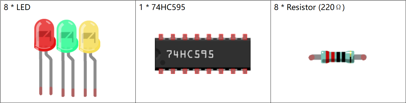
Principle
74HC595
The 74HC595 consists of an 8−bit shift register and a storage register with three−state parallel outputs. It converts serial input into parallel output so you can save IO ports of an MCU.
When MR (pin10) is high level and OE (pin13) is low level, data is input in the rising edge of SHcp and goes to the memory register through the rising edge of SHcp. If the two clocks are connected together, the shift register is always one pulse earlier than the memory register. There is a serial shift input pin (Ds), a serial output pin (Q) and an asynchronous reset button (low level) in the memory register. The memory register outputs a Bus with a parallel 8-bit and in three states. When OE is enabled (low level), the data in memory register is output to the bus.
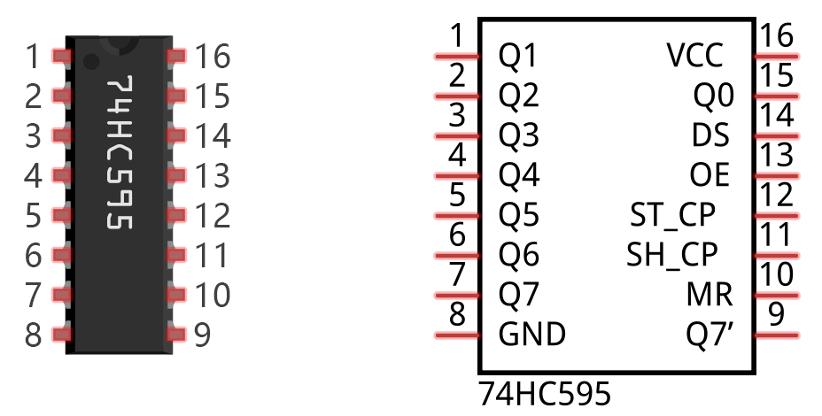
Pins of 74HC595 and their Functions:
Q0-Q7: 8-bit parallel data output pins, able to control 8 LEDs or 8 pins of 7-Segment Display directly.
Q7’: Series output pin, connected to DS of another 74HC595 to connect multiple 74HC595s in series.
MR: Reset pin, active at low level;
SHcp: Time sequence input of shift register. On the rising edge, the data in shift register moves successively one bit, i.e. data in Q1 moves to Q2, and so forth. While on the falling edge, the data in shift register remain unchanged.
STcp: Time sequence input of storage register. On the rising edge, data in the shift register moves into memory register.
OE: Output enable pin, active at low level.
DS: Serial data input pin.
VCC: Positive supply voltage.
GND: Ground.
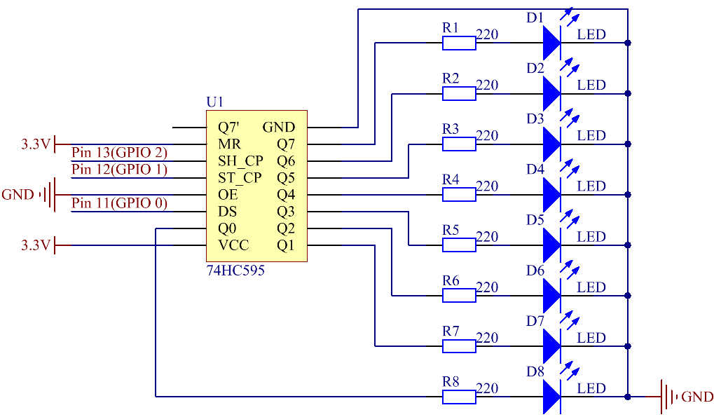
Schematic Diagram
In the experiment MR is connected to 3.3V (HIGH Level) and OE to GND (LOW Level). Therefore, the data is input into the rising edge of SHcp and enters the memory register through the rising edge. In the rising edge of the SHcp, the data in the shift register moves successively one bit in one time, i.e. data in Q1 moves to Q2, and so forth. In the rising edge of STcp, data in the shift register moves into the memory register. All data will be moved to the memory register 8 times. Then the data in the memory register is output to the bus (Q0-Q7).
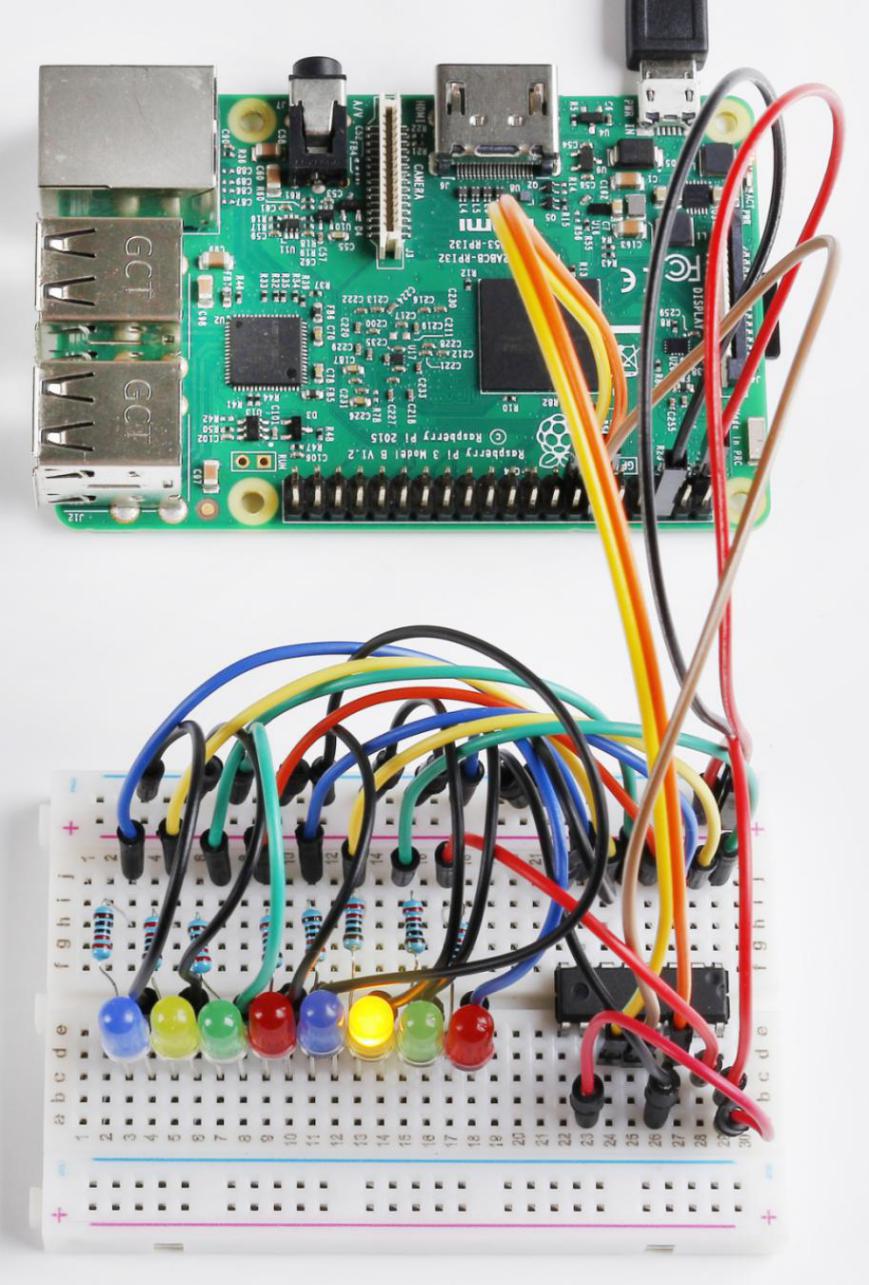
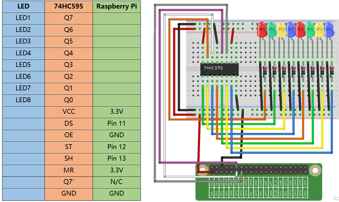
Build the Circuit
Note
Recognize the direction of the chip according to the concave on it.
For C Language Users
Command
1. Go to the folder of the code.
cd /home/pi/electronic-kit/for-raspberry-pi/c/Lesson_18_Driving_Leds_by_74hc595
2. Compile the code.
gcc 18_74hc595.c -lwiringPi
3. Run the executable file.
sudo ./a.out
As the code runs, you can see these eight LEDs are lit up from left to right, and then all LEDs light up and flash 3 times. After that, these eight LEDs are lit from right to left, then they all turn on before flashing 3 times. This loop continues in this way.
Note
If it does not work after running, or there is an error prompt: "wiringPi.h: No such file or directory", please refer to C code is not working?.
Code
#include <wiringPi.h>
#include <stdio.h>

#define   SDI   0   //serial data input
#define   RCLK  1   //memory clock input(STCP)
#define   SRCLK 2   //shift register clock input(SHCP)

unsigned char LED[8] = {0x01,0x02,0x04,0x08,0x10,0x20,0x40,0x80};

void pulse(int pin){
    digitalWrite(pin, 0);
    digitalWrite(pin, 1);
}

void SIPO(unsigned char byte){
    int i;
    for(i=0;i<8;i++){
        digitalWrite(SDI, ((byte & (0x80 >> i)) > 0));
        pulse(SRCLK);
    }
}

void init(void){
    pinMode(SDI, OUTPUT);
    pinMode(RCLK, OUTPUT);
    pinMode(SRCLK, OUTPUT);

    digitalWrite(SDI, 0);
    digitalWrite(RCLK, 0);
    digitalWrite(SRCLK, 0);
}

int main(void){
    int i;

    if(wiringPiSetup() == -1){ //when initialize wiring failed, print message to screen
        printf("setup wiringPi failed !");
        return 1;
    }

    init();

    while(1){
        for(i=0;i<8;i++){
            SIPO(LED[i]);
            pulse(RCLK);
            delay(150);
        }
        delay(500);

        for(i=0;i<3;i++){
            SIPO(0xff);
            pulse(RCLK);
            delay(100);
            SIPO(0x00);
            pulse(RCLK);
            delay(100);
        }
        delay(500);

        for(i=0;i<8;i++){
            SIPO(LED[8-i-1]);
            pulse(RCLK);
            delay(150);
        }
        delay(500);

        for(i=0;i<3;i++){
            SIPO(0xff);
            pulse(RCLK);
            delay(100);
            SIPO(0x00);
            pulse(RCLK);
            delay(100);
        }
        delay(500);
    }
    return 0;
}
Code Explanation
10.void pulse(int pin){
11.    digitalWrite(pin, 0);
12.    digitalWrite(pin, 1);
13.}
Define an pulse function to generate an pulse.
15.void SIPO(unsigned char byte){
16.    int i;
17.    for(i=0;i<8;i++){
18.        digitalWrite(SDI, ((byte & (0x80 >> i)) > 0));
19.        pulse(SRCLK);
20.    }
21.}
The function SIPO is used to assign the byte data to SDI(DS) by bits.
Among them, the inequality in statement digitalWrite() ((byte & (0x80>>i))>0) is used to confirm each value written into the register and it realizes the function by Shift operator (>>).
For example, if byte=0x01:
When the condition “i=0” is met, 0x80(1000 0000)>>0 becomes 0x80(1000 0000), if byte&0x80=0, the inequality is false, and output 0 (false).
If “i=1” is true, 0x80>>1 changes into 0x40(0100 0000); when byte&0x40=0, output 0.
Deduce the rest from this, when and only when “i=8” is met, 0x80>>8 is 0x01(0000 0001), byte&0x01=1, and output 1(true).
Pulse(SRCLK) generates a rising edge pulse on input pin of shift register to shift the 8 bit data on SDI to shift register successively.
In a word, this for loop produces 8 times to shift the 8 bits of 0000 0001 to shift register.
23.void init(void){
24.    pinMode(SDI, OUTPUT);
25.    pinMode(RCLK, OUTPUT);
26.    pinMode(SRCLK, OUTPUT);
27.
28.    digitalWrite(SDI, 0);
29.    digitalWrite(RCLK, 0);
30.    digitalWrite(SRCLK, 0);
31.}
Initialize pins. Set all control pins of 74HC595 to output mode and initialize them to low level. At the same time, the LEDs are set to output mode, default low level.
44.        for(i=0;i<8;i++){
45.            SIPO(LED[i]);
46.            pulse(RCLK);
47.            delay(150);
48.        }
Use the for loop to count 8 times in cycle, and write a 1-bit data to the SDI each time.
When i=0, LED[0]=0x01(0000 0001), through the function SIPO(LED[0]), shifts the 8 bits of 0x01 to shift register successively. Pulse(SRCLK) generates a rising edge signal on input pin of storage register to shift the 0x01 on shift register to storage register at once. Then the data in the memory register are output to the bus (Q7-Q0), so you’ll see the LED on Q0 is lit up. After loops, output all eight elements in the array LED[i] to the bus (Q7-Q0), and you’ll see eight LEDs turning on from left to right.
51.        for(i=0;i<3;i++){
52.            SIPO(0xff);
53.            pulse(RCLK);
54.            delay(100);
55.            SIPO(0x00);
56.            pulse(RCLK);
57.            delay(100);
58.        }
In this part, the for loop is used to three times repeat the program in for() statement. SIPO(0xff) means 8 LEDs are lit up, SIPO(0x00) represents 8 LEDs turn off. That is, let 8 LEDs turn off 3 times simultaneously.
61.        for(i=0;i<8;i++){
62.            SIPO(LED[8-i-1]);
63.            pulse(RCLK);
64.            delay(150);
65.        }
By the same token, this for loop allows 8 LEDs be lit up one by one in reverse order. Here, i gradually increases from 0, and 8-i-1 gradually decreases. SIPO(LED[8-i-1]) can be used to call the data in the LED[] array from back to front so that you can get 8 LEDs lit up one by one in reverse order.
68.        for(i=0;i<3;i++){
69.            SIPO(0xff);
70.            pulse(RCLK);
71.            delay(100);
72.            SIPO(0x00);
73.            pulse(RCLK);
74.            delay(100);
75.        }
Then, make the eight LEDs turn on or off 3 times simultaneously.
For Python Language Users
Command
1. Go to the folder of the code.
cd /home/pi/electronic-kit/for-raspberry-pi/python
2. Run the code.
sudo python3 18_74HC595.py
As the code runs, you can see these eight LEDs are lit up from left to right, and then all LEDs light up and flash 3 times. After that, these eight LEDs are lit from right to left, then they all turn on before flashing 3 times. This loop continues in this way.
Code
Note
You can Modify/Reset/Copy/Run/Stop the code below. But before that, you need to go to source code path like electronic-kit/for-raspberry-pi/python. After modifying the code, you can run it directly to see the effect.
#!/usr/bin/env python3
#================================================
#
# This program is for SunFounder SuperKit for Rpi.
#
# Extend use of 8 LED with 74HC595.
#
# Change the WhichLeds and sleeptime value under
# loop() function to change LED mode and speed.
#
#=================================================
import RPi.GPIO as GPIO
import time
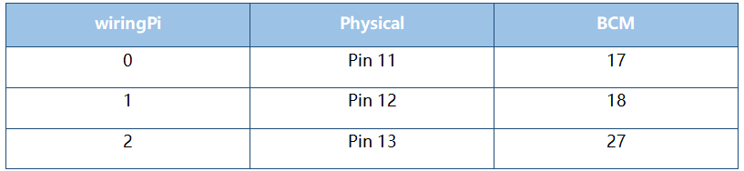
SDI = 17
RCLK = 18
SRCLK = 27
#=============== LED Mode Defne ================
# You can define yourself, in binay, and convert it to Hex
# 8 bits a group, 0 means off, 1 means on
# like : 0101 0101, means LED1, 3, 5, 7 are on.(from left to right)
# and convert to 0x55.
LED0 = [0x01,0x02,0x04,0x08,0x10,0x20,0x40,0x80] #original mode
BLINK = [0xff,0x00,0xff,0x00,0xff,0x00] #blink
#=================================================
def print_message():
print ("========================================")
print ("| LEDs with 74HC595 |")
print ("| ------------------------------ |")
print ("| SDI connect to GPIO 0 |")
print ("| RCLK connect to GPIO 1 |")
print ("| SRCLK connect to GPIO 2 |")
print ("| |")
print ("| Control LEDs with 74HC595 |")
print ("| |")
print ("| SunFounder|")
print ("========================================\n")
print ('Program is running...')
print ('Please press Ctrl+C to end the program...')
#input ("Press Enter to begin\n")
def setup():
GPIO.setmode(GPIO.BCM) # Number GPIOs by its BCM location
GPIO.setup(SDI, GPIO.OUT, initial=GPIO.LOW)
GPIO.setup(RCLK, GPIO.OUT, initial=GPIO.LOW)
GPIO.setup(SRCLK, GPIO.OUT, initial=GPIO.LOW)
# Shift the data to 74HC595
def hc595_shift(dat):
for bit in range(0, 8):
GPIO.output(SDI, 0x80 & (dat << bit))
GPIO.output(SRCLK, GPIO.HIGH)
time.sleep(0.001)
GPIO.output(SRCLK, GPIO.LOW)
GPIO.output(RCLK, GPIO.HIGH)
time.sleep(0.001)
GPIO.output(RCLK, GPIO.LOW)
def main():
print_message()
mode = LED0
sleeptime = 0.15 # Change speed, lower value, faster speed
blink_sleeptime = 0.15
while True:
# Change LED status from mode
for onoff in mode:
hc595_shift(onoff)
time.sleep(sleeptime)
for onoff in BLINK:
hc595_shift(onoff)
time.sleep(blink_sleeptime)
# Change LED status from mode reverse
for onoff in reversed(mode):
hc595_shift(onoff)
time.sleep(sleeptime)
for onoff in BLINK:
hc595_shift(onoff)
time.sleep(blink_sleeptime)
def destroy():
GPIO.cleanup()
if __name__ == '__main__':
setup()
try:
main()
except KeyboardInterrupt:
destroy()
Code Explanation
8.LED0 = [0x01,0x02,0x04,0x08,0x10,0x20,0x40,0x80] #original mode
Use array to define LED flashing mode, you can also customize several hexadecimals to light up 8 LEDs.
11.def setup():
1.     GPIO.setmode(GPIO.BCM)    # Number GPIOs by its BCM location
2.     GPIO.setup(SDI, GPIO.OUT, initial=GPIO.LOW)
3.     GPIO.setup(RCLK, GPIO.OUT, initial=GPIO.LOW)
4.     GPIO.setup(SRCLK, GPIO.OUT, initial=GPIO.LOW)
Initialize pins. Set all control pins of 74HC595 to output mode and initialize them to low level. At the same time, the LED lights are set to output mode, default low level.
18.def hc595_shift(dat):
Define a function hc595_shift() to output the 8 bits of dat to Q0-Q7.
1.  for bit in range(0, 8):
2.         GPIO.output(SDI, 0x80 & (dat << bit))
3.         GPIO.output(SRCLK, GPIO.HIGH)
4.         time.sleep(0.001)
5.         GPIO.output(SRCLK, GPIO.LOW)
Assign the dat to SDI(DS) according to bits. Pin SRCLK will convert from low to high, and generate a rising edge pulse, then shift the data in pin SDI to shift register. Execute the loop 8 times to shift the 8 bits of dat to the shift register in proper order.
1.     GPIO.output(RCLK, GPIO.HIGH)
2.     time.sleep(0.001)
3.     GPIO.output(RCLK, GPIO.LOW)
Pin RCLK converts from low to high and generate a rising edge, then shift data from shift register to storage register. Finally the data in the memory register is output to the bus (Q0-Q7).
1.         for onoff in mode:
2.             hc595_shift(onoff)
3.             time.sleep(sleeptime)
Here we use a onoff variable to control the LED that changes within the range of mode, and hc595_shift (onoff) means lighting up LED one by one. For example, when mode is the first datum in LED0, or 0x01, onoff = mode = 0x01 = 00000001. In this course, the LED is lit by high level. To put it another way, it is Hc595_shift (onoff) = hc595_shift (00000001) that lights up the last LED. Along the same vein, when the value of mode is the second datum of LED0 (onoff = 0x02 = 00000010), the second last LED turns on.
1.         for onoff in reversed(mode):
2.             hc595_shift(onoff)
3.             time.sleep(sleeptime)
According to the same principle, a reversed is used here to get LEDs lit up in reverse order.
1.         for onoff in BLINK:
2.             hc595_shift(onoff)
3.             time.sleep(blink_sleeptime)
In the same way, light up 8 LEDs; exactly, 8 LEDs are turned on or off 3 times synchronously in the same pattern as that of the LEDs in the BLINK array.
Phenomenon Picture