Note
Hello, welcome to the SunFounder Raspberry Pi & Arduino & ESP32 Enthusiasts Community on Facebook! Dive deeper into Raspberry Pi, Arduino, and ESP32 with fellow enthusiasts.
Why Join?
Expert Support: Solve post-sale issues and technical challenges with help from our community and team.
Learn & Share: Exchange tips and tutorials to enhance your skills.
Exclusive Previews: Get early access to new product announcements and sneak peeks.
Special Discounts: Enjoy exclusive discounts on our newest products.
Festive Promotions and Giveaways: Take part in giveaways and holiday promotions.
👉 Ready to explore and create with us? Click [here] and join today!
Lesson 6 Tilt Switch
Introduction
In this lesson, we’ll learn a new switch component, tilt switch. Here we apply two LEDs to indicate the current state of tilt switch. You can also use this kind of switch to make a sense light with the clamshell box.
Newly Added Components
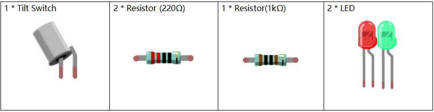
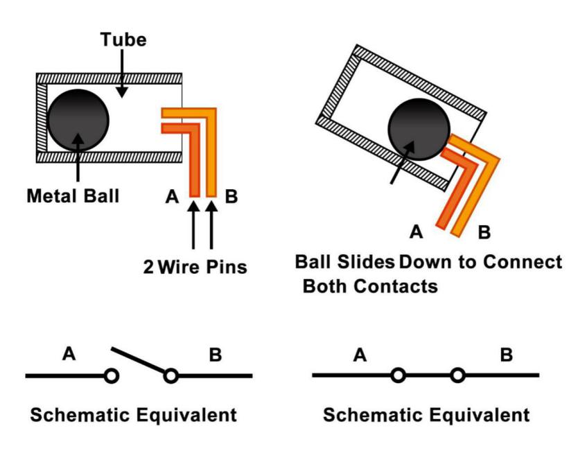
Principle
The principle is very simple. When the switch is tilted in a certain angle, the ball inside rolls down and touches the two contacts connected to the pins outside, thus triggering circuits. Otherwise the ball will stay away from the contacts, thus breaking the circuits.
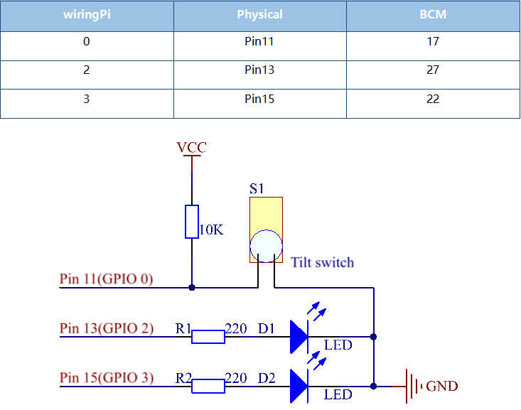
Schematic Diagram
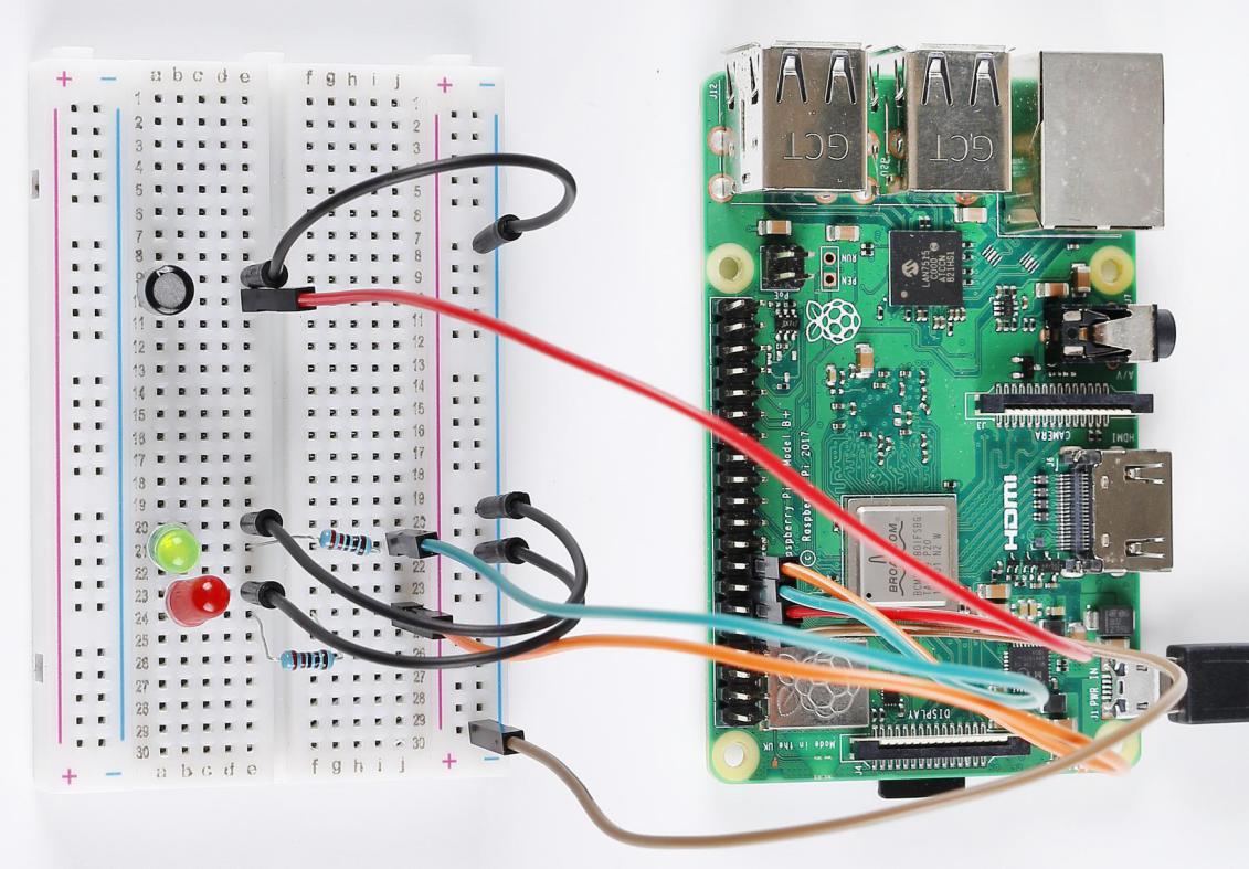
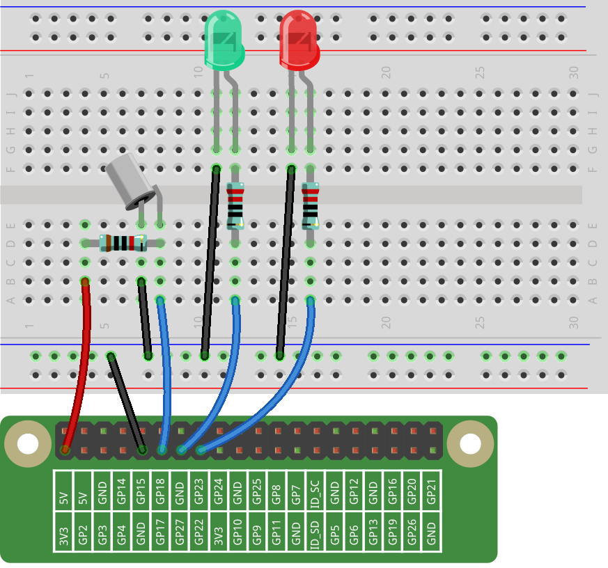
Build the Circuit
For C Language Users
Command
1. Go to the folder of the code.
cd /home/pi/electronic-kit/for-raspberry-pi/c/Lesson_6_TiltSwitch
2. Compile the code.
gcc 6_Tilt.c -lwiringPi
3. Run the executable file.
sudo ./a.out
When the tilt switch is level, the green LED turns on. If you tilt the switch, the red LED will turn on.
Note
If it does not work after running, or there is an error prompt: "wiringPi.h: No such file or directory", please refer to C code is not working?.
Code
#include <wiringPi.h>
#include <stdio.h>

#define TiltPin     0
#define Gpin        2
#define Rpin        3

int main(void)
{
    if(wiringPiSetup() == -1){ //when initialize wiring failed,print message to screen
        printf("setup wiringPi failed !");
        return 1;
    }

    pinMode(TiltPin, INPUT);
    pinMode(Gpin, OUTPUT);
    pinMode(Rpin, OUTPUT);

    while(1){

        if(1 == digitalRead(TiltPin)){
            delay(10);
            if(1 == digitalRead(TiltPin)){
                digitalWrite(Rpin, HIGH);
                digitalWrite(Gpin, LOW);
                printf("RED\n");
            }
        }
        else if(0 == digitalRead(TiltPin)){
            delay(10);
            if(0 == digitalRead(TiltPin)){
                while(!digitalRead(TiltPin));
                digitalWrite(Rpin, LOW);
                digitalWrite(Gpin, HIGH);
                printf("GREEN\n");
            }
        }
    }
    return 0;
}
Code Explanation
15.    pinMode(TiltPin, INPUT);
16.    pinMode(Gpin, OUTPUT);
17.    pinMode(Rpin, OUTPUT);
Initialize pins, then set the pin of tilt switch to INPUT mode, and LEDs to OUTPUT mode.
21. if(1 == digitalRead(TiltPin)){
It is used to judge whether the tilt switch is tilted or not. The value of TiltPin is firstly read, if it is equal to 1, the codes inside the if() statement run; otherwise, the codes of if are skipped.
21.    if(1 == digitalRead(TiltPin)){
22.            delay(10);
23.            if(1 == digitalRead(TiltPin)){
24.                digitalWrite(Rpin, HIGH);
25.                digitalWrite(Gpin, LOW);
26.                printf("RED\n");
27.            }
28.        }
When the tilt is tilted, the tilt switch is on; the Raspberry Pi reads a high level at the tilt pin, so the red LED is on and green LED off.
29.        else if(0 == digitalRead(TiltPin)){
30.            delay(10);
31.            if(0 == digitalRead(TiltPin)){
32.                while(!digitalRead(TiltPin));
33.                digitalWrite(Rpin, LOW);
34.                digitalWrite(Gpin, HIGH);
35.                printf("GREEN\n");
36.            }
37.        }
When the tilt is level, the tilt switch is off; the Raspberry Pi reads a low level at the tilt pin, so the red LED is off and green LED on.
For Python Language Users
Command
1. Go to the folder of the code.
cd /home/pi/electronic-kit/for-raspberry-pi/python
2. Run the code.
sudo python3 6_Tilt.py
When the tilt switch is level, the green LED turns on. If you tilt the switch, the red LED will turn on.
code
Note
You can Modify/Reset/Copy/Run/Stop the code below. But before that, you need to go to source code path like electronic-kit/for-raspberry-pi/python. After modifying the code, you can run it directly to see the effect.
import RPi.GPIO as GPIO

TiltPin = 17
Gpin   = 27
Rpin   = 22

def setup():
    GPIO.setmode(GPIO.BCM)
    GPIO.setup(Gpin, GPIO.OUT,initial=GPIO.HIGH)
    GPIO.setup(Rpin, GPIO.OUT,initial=GPIO.LOW)
    GPIO.setup(TiltPin, GPIO.IN)
    GPIO.add_event_detect(TiltPin, GPIO.BOTH, callback=detect, bouncetime=200)

def Led(x):
    if x == 0:
        GPIO.output(Rpin, 1)
        GPIO.output(Gpin, 0)
    if x == 1:
        GPIO.output(Rpin, 0)
        GPIO.output(Gpin, 1)

def Print(x):
    if x == 0:
        print ('    *************')
        print ('    *   Tilt!   *')
        print ('    *************')

def detect(chn):
    Led(GPIO.input(TiltPin))
    Print(GPIO.input(TiltPin))

def loop():
    while True:
        pass

def destroy():
    GPIO.output(Gpin, GPIO.LOW)       # Green LED off
    GPIO.output(Rpin, GPIO.LOW)       # Red LED off
    GPIO.cleanup()                     # Release resource

if __name__ == '__main__':     # Program start from here
    setup()
    try:
        loop()
        # When 'Ctrl+C' is pressed, the child program destroy() will be  executed.
    except KeyboardInterrupt:
        destroy()
Code Explanation
12. GPIO.add_event_detect(TiltPin, GPIO.BOTH, callback=detect, bouncetime=200)
Set up a falling detect on TiltPin, and callback function to detect. Here bouncetime is to add rise threshold detection on the channel and ignore edge operations less than 200ms caused by switch jitter.
13.def Led(x):
14.    if x == 0:
15.        GPIO.output(Rpin, 1)
16.        GPIO.output(Gpin, 0)
17.    if x == 1:
18.        GPIO.output(Rpin, 0)
19.        GPIO.output(Gpin, 1)
Define a Led() function to set the mode of the two LEDs. When x = 0, the red LED goes on and the green light goes off; when x = 1, the red LED goes off, the green LED goes on. When the function is called, the mode of the LED can be set directly with the statement Led(1) or Led(0).
28.def detect(chn):
29.    Led(GPIO.input(TiltPin))
30.    Print(GPIO.input(TiltPin))
This is a callback function that executes when a trigger is detected. Assign the current TiltPin state (0 or 1) to the Led function, that is, pass parameters to the Led function. The Led function then performs the corresponding operation on the LEDs.
Phenomenon Picture