Note
Hello, welcome to the SunFounder Raspberry Pi & Arduino & ESP32 Enthusiasts Community on Facebook! Dive deeper into Raspberry Pi, Arduino, and ESP32 with fellow enthusiasts.
Why Join?
Expert Support: Solve post-sale issues and technical challenges with help from our community and team.
Learn & Share: Exchange tips and tutorials to enhance your skills.
Exclusive Previews: Get early access to new product announcements and sneak peeks.
Special Discounts: Enjoy exclusive discounts on our newest products.
Festive Promotions and Giveaways: Take part in giveaways and holiday promotions.
👉 Ready to explore and create with us? Click [here] and join today!
Lesson 20 Traffic Light
Introduction
In last lesson, we learned how to use a 74HC595 chip to drive a 7-Segment Display. Based on that, we can apply it more widely now, such as making a simple traffic light. Now let’s get started!
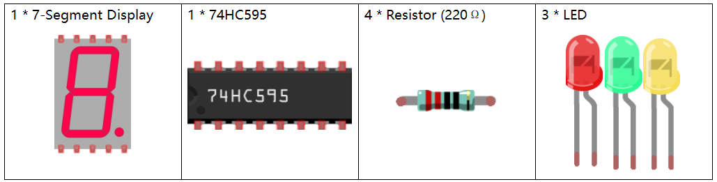
Newly Added Components
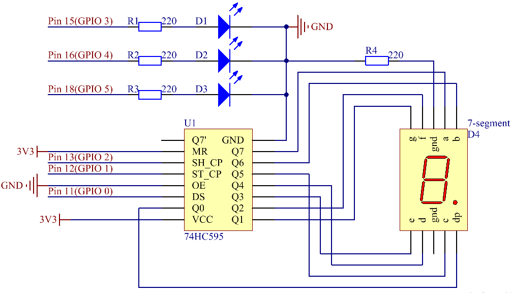
Schematic Diagram

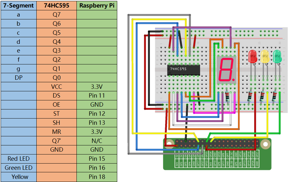
Build the Circuit
For C Language Users
Command
1. Go to the folder of the code.
cd /home/pi/electronic-kit/for-raspberry-pi/c/Lesson_20_TrafficLight
2. Compile the code.
gcc 20_TrafficLight.c -lwiringPi
3. Run the executable file.
sudo ./a.out
You can see the following phenomenon of traffic lights. The red LED lights up for 9 seconds, green LED for 5s, and yellow LED for 3s.
Note
If it does not work after running, or there is an error prompt: "wiringPi.h: No such file or directory", please refer to C code is not working?.
Code
#include <wiringPi.h>
#include <stdio.h>
#include <wiringShift.h>
#include <signal.h>
#include <unistd.h>
#define     SDI     0   //serial data input(DS)
#define     RCLK    1   //memory clock input(STCP)
#define     SRCLK    2    //shift register clock input(SHCP)
const int ledPin[]={3,4,5};   //Define 3 LED pin(Red, Green, Yellow)
unsigned char SegCode[17] = {0x3f,0x06,0x5b,0x4f,0x66,0x6d,0x7d,0x07,0x7f,0x6f,0x77,0x7c,0x39,0x5e,0x79,0x71,0x80};

int greentime = 5;
int yellowtime = 3;
int redtime = 9;
int colorState = 0;
char *lightColor[]={"Red","Green","Yellow"};
int counter = 9;

void init(void){
    pinMode(SDI, OUTPUT);
    pinMode(RCLK, OUTPUT);
    pinMode(SRCLK, OUTPUT);

    digitalWrite(SDI, 0);
    digitalWrite(RCLK, 0);
    digitalWrite(SRCLK, 0);

      for(int i=0;i<3;i++){
        pinMode(ledPin[i],OUTPUT);
        digitalWrite(ledPin[i],LOW);
    }
}

void hc595_shift(unsigned char dat){
    int i;
    for(i=0;i<8;i++){
        digitalWrite(SDI, 0x80 & (dat << i));
        digitalWrite(SRCLK, 1);
        delay(1);
        digitalWrite(SRCLK, 0);
    }
        digitalWrite(RCLK, 1);
        delay(1);
        digitalWrite(RCLK, 0);
}

void timer(int  sig){       //Timer function
    if(sig == SIGALRM){
        counter --;
        alarm(1);
        if(counter == 0){
            if(colorState == 0) counter = greentime;
            if(colorState == 1) counter = yellowtime;
            if(colorState == 2) counter = redtime;
            colorState = (colorState+1)%3;
        }
        printf("counter : %d \t light color: %s \n",counter,lightColor[colorState]);
    }
}

void display(int num)
{
    hc595_shift(SegCode[num%10]);
    delay(1);
}

void lightup(int state)
{
    for(int i=0;i<3;i++){
        digitalWrite(ledPin[i],LOW);
    }
        digitalWrite(ledPin[state],HIGH);
}

int main(void)
{
    int i;

    if(wiringPiSetup() == -1){ //when initialize wiring failed,print message to screen
        printf("setup wiringPi failed !");
        return 1;
    }

    init();

    signal(SIGALRM,timer);  //configure the timer
    alarm(1);               //set the time of timer to 1s
    while(1){
        display(counter);
        lightup(colorState);
    }
    return 0;
}
Code Explanation
12.int greentime = 5;
13.int yellowtime = 3;
14.int redtime = 9;
Define the duration of lighting of three LEDs. Since what we use is a 7-Segment Display here, we shorten the length of seconds of lighting of traffic lights, setting the green LED to light up for 5 seconds, the yellow LED to 3 seconds, and the red LED to 9 seconds.
15.int colorState = 0;
16.int counter = 9;
The variable colorState corresponds to the state of the traffic lights, and we only need to do a simple calculation of colorState to indicate the order change of the state of the traffic lights. The Variable counter is used to count down the time to each traffic light status and will be output on a 7-Segment Display.
19.void init(void){
20.    pinMode(SDI, OUTPUT);
21.    pinMode(RCLK, OUTPUT);
22.    pinMode(SRCLK, OUTPUT);
23.
24.    digitalWrite(SDI, 0);
25.    digitalWrite(RCLK, 0);
26.    digitalWrite(SRCLK, 0);
27.
28.      for(int i=0;i<3;i++){
29.        pinMode(ledPin[i],OUTPUT);
30.        digitalWrite(ledPin[i],LOW);
31.    }
32.}
Initialize pins. Set all control pins of 74HC595 to output mode and initialize them to low level. At the same time, the LEDs are set to output mode, default low level.
47.void timer(int  sig){
48.    if(sig == SIGALRM){
49.        counter --;
50.        alarm(1);
51.        if(counter == 0){
52.            if(colorState == 0) counter = greentime;
53.            if(colorState == 1) counter = yellowtime;
54.            if(colorState == 2) counter = redtime;
55.            colorState = (colorState+1)%3;
56.        }
57.        printf("counter : %d \t light color: %s \n",counter,lightColor[colorState]);
58.    }
59.}
On this timer, counter decreases gradually with every second passing, and when it goes to 0, the state of the traffic light changes accordingly.
67.void lightup(int state)
68.{
69.    for(int i=0;i<3;i++){
70.        digitalWrite(ledPin[i],LOW);
71.    }
72.        digitalWrite(ledPin[state],HIGH);
73.}
The function is to turn off all the lights first, and then light up the corresponding LED according to the value of the traffic light state.
For Python Language Users
Command
1. Go to the folder of the code.
cd /home/pi/electronic-kit/for-raspberry-pi/python
2. Run the code.
sudo python3 20_TrafficLight.py
You can see the following phenomenon of traffic lights. The red LED lights up for 9 seconds, green LED for 5s, and yellow LED for 3s.
Code
Note
You can Modify/Reset/Copy/Run/Stop the code below. But before that, you need to go to source code path like electronic-kit/for-raspberry-pi/python. After modifying the code, you can run it directly to see the effect.
import RPi.GPIO as GPIO
import time
import threading

#define the pins connect to 74HC595
SDI   = 17      #serial data input(DS)
RCLK  = 18      #memory clock input(STCP)
SRCLK = 27       #shift register clock input(SHCP)
number = (0x3f,0x06,0x5b,0x4f,0x66,0x6d,0x7d,0x07,0x7f,0x6f,0x77,0x7c,0x39,0x5e,0x79,0x71,0x80)

ledPin =(22,23,24)

greenLight = 5
yellowLight = 3
redLight = 9
lightColor=("Red","Green","Yellow")

colorState=0
counter = 9
t = 0

def setup():
    GPIO.setmode(GPIO.BCM)
    GPIO.setup(SDI, GPIO.OUT)
    GPIO.setup(RCLK, GPIO.OUT)
    GPIO.setup(SRCLK, GPIO.OUT)
    for pin in ledPin:
        GPIO.setup(pin,GPIO.OUT)


def hc595_shift(dat):
    for bit in range(0, 8):
        GPIO.output(SDI, 0x80 & (dat << bit))
        GPIO.output(SRCLK, GPIO.HIGH)
        GPIO.output(SRCLK, GPIO.LOW)
    GPIO.output(RCLK, GPIO.HIGH)
    GPIO.output(RCLK, GPIO.LOW)

def display(num):
    hc595_shift(0xff)
    hc595_shift(number[num%10])
    time.sleep(0.003)


def timer():        #timer function
    global counter
    global colorState
    global t
    t = threading.Timer(1.0,timer)
    t.start()
    counter-=1
    if (counter is 0):
        if(colorState is 0):
            counter= greenLight
        if(colorState is 1):
            counter=yellowLight
        if (colorState is 2):
            counter=redLight
        colorState=(colorState+1)%3
    print ("counter : %d    color: %s "%(counter,lightColor[colorState]))

def lightup(state):
    for i in range(0,3):
        GPIO.output(ledPin[i], GPIO.LOW)
    GPIO.output(ledPin[state], GPIO.HIGH)

def loop():
    global t
    global counter
    global colorState
    t = threading.Timer(1.0,timer)
    t.start()
    while True:
        display(counter)
        lightup(colorState)

def destroy():   # When "Ctrl+C" is pressed, the function is executed.
    global t
    GPIO.cleanup()
    t.cancel()      #cancel the timer

if __name__ == '__main__': # Program starting from here
    setup()
    try:
        loop()
    except KeyboardInterrupt:
        destroy()
Code Explanation
13.greenLight = 5
14.yellowLight = 3
15.redLight = 9
Define the duration of lighting of three LEDs. Since what we use is a 7-Segment Display here, we shorten the length of seconds of lighting of traffic LEDs, setting the green LED to light up for 5 seconds, the yellow LED to 3 seconds, and the red LED to 9 seconds.
18.colorState=0
19.counter = 9
The variable colorState corresponds to the state of the traffic LEDs, and we only need to do a simple calculation of colorState to indicate the order change of the state of the traffic LEDs.
counter is used to count down the time to each traffic LED status and will be output on a 7-Segment Display.
45.def timer():        #timer function
46.    global counter
47.    global colorState
48.    global t
49.    t = threading.Timer(1.0,timer)
50.    t.start()
51.    counter-=1
52.    if (counter is 0):
53.        if(colorState is 0):
54.            counter= greenLight
55.        if(colorState is 1):
56.            counter=yellowLight
57.        if (colorState is 2):
58.            counter=redLight
59.        colorState=(colorState+1)%3
60.    print ("counter : %d    color: %s "%(counter,lightColor[colorState]))
On this timer, counter decreases gradually with every second passing, and when it goes to 0, the state of the traffic LED changes accordingly.
62.def lightup(state):
63.    for i in range(0,3):
64.        GPIO.output(ledPin[i], GPIO.LOW)
65.    GPIO.output(ledPin[state], GPIO.HIGH)
The function is to turn off all the LEDs first, and then light up the corresponding LED according to the value of the traffic LED state.
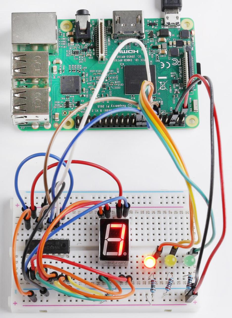
Phenomenon Picture