Note
Hello, welcome to the SunFounder Raspberry Pi & Arduino & ESP32 Enthusiasts Community on Facebook! Dive deeper into Raspberry Pi, Arduino, and ESP32 with fellow enthusiasts.
Why Join?
Expert Support: Solve post-sale issues and technical challenges with help from our community and team.
Learn & Share: Exchange tips and tutorials to enhance your skills.
Exclusive Previews: Get early access to new product announcements and sneak peeks.
Special Discounts: Enjoy exclusive discounts on our newest products.
Festive Promotions and Giveaways: Take part in giveaways and holiday promotions.
👉 Ready to explore and create with us? Click [here] and join today!
Lesson 9 4N35
Introduction
In this lesson, let’s learn the operational principle of 4N35 chip. We analyze the principle in this way: using 4N35 chip to drive a LED, and then explaining the phenomenon of LED and the internal structure of the chip.
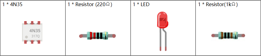
Newly Added Components
Principle
4N35
4N35 is a general-purpose optocoupler. It consists of gallium arsenide infrared LED and a silicon NPN phototransistor. What an optocoupler does is to break the connection between signal source and signal receiver, so as to stop electrical interference. 4N35 can be used in AV conversion audio circuits that is widely used in electrical isolation of a general optocoupler.

See the internal structure of the 4N35 above. Pin 1 and 2 are connected to an infrared LED. When the LED is electrified, it’ll emit infrared rays. To protect the LED from burning, usually a resistor (about 1K) is connected to pin 1. Then the NPN phototransistor is power on when receiving the rays, and then it can control the load connected to the phototransistor. Even when the load short circuit occurs, it won’t affect the control board, thus realizing good electrical isolation.
Schematic Diagram
In this experiment, use an LED as the load connected to the NPN phototransistor. In program, a LOW level is given to Pin 11, then the infrared LED will emit infrared rays. After that, the phototransistor receives infrared rays and gets electrified, and the LED cathode is LOW, thus turning on the LED.

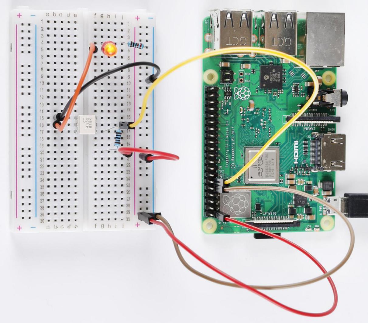
Build the Circuit
Note
pay attention to the direction of the chip by the concave on it.

For C Language Users
Command
1. Go to the folder of the code.
cd /home/pi/electronic-kit/for-raspberry-pi/c/Lesson_9_4N35
2. Compile the code.
gcc 9_4N35.c -lwiringPi
3. Run the executable file.
sudo ./a.out
You will see the LED blinking.
Note
If it does not work after running, or there is an error prompt: "wiringPi.h: No such file or directory", please refer to C code is not working?.
Code
#include <wiringPi.h>
#include <stdio.h>

#define OptoPin  0

int main(void)
{
    // When initialize wiring failed, print message to screen
    if(wiringPiSetup() == -1){
        printf("setup wiringPi failed !");
        return 1;
    }

    pinMode(OptoPin,OUTPUT);

    while(1){
        // Turn LED off
        digitalWrite(OptoPin, HIGH);
        delay(500);
        // Turn LED on
        digitalWrite(OptoPin, LOW);
        delay(500);
    }
    return 0;
}
Code Explanation
14. pinMode(OptoPin,OUTPUT);
Initialize pins. Set the output pin of 4N35, Optopin to OUTPUT mode.
18. digitalWrite(OptoPin, HIGH);
Set OptoPin as LOW (0V), thus the optocoupler is energized, and the pin connected to LED conduct to low level. Then the LED will light up.
21. digitalWrite(OptoPin, LOW);
Set OptoPin as HIGH (3.3V), thus the optocoupler is not energized, and the pin connected to LED cannot conduct to low level. Then the LED goes out.
For Python Language Users
Command
1. Go to the folder of the code.
cd /home/pi/electronic-kit/for-raspberry-pi/python
2. Run the code.
sudo python3 9_4N35.py
You will see the LED blinking.
Code
Note
You can Modify/Reset/Copy/Run/Stop the code below. But before that, you need to go to source code path like electronic-kit/for-raspberry-pi/python. After modifying the code, you can run it directly to see the effect.
import RPi.GPIO as GPIO
import time

Pin_4N35 = 17

# Define a setup function for some setup
def setup():
    GPIO.setmode(GPIO.BCM)
    GPIO.setup(Pin_4N35, GPIO.OUT, initial=GPIO.LOW)

# Define a main function for main process
def main():
    while True:
        # Turn off LED
        GPIO.output(Pin_4N35, GPIO.HIGH)
        time.sleep(0.5)
        # Turn on LED
        GPIO.output(Pin_4N35, GPIO.LOW)
        time.sleep(0.5)

def destroy():
    # Turn off LED
    GPIO.output(Pin_4N35, GPIO.HIGH)
    # Release resource
    GPIO.cleanup()

# If run this script directly, do:
if __name__ == '__main__':
    setup()
    try:
        main()
    # When 'Ctrl+C' is pressed, the child program
    # destroy() will be  executed.
    except KeyboardInterrupt:
        destroy()
Code Explanation
1. GPIO.output(Pin_4N35, GPIO.HIGH)
Set OptoPin as high level (3.3V), thus the optocoupler is not energized, and the pin connected to LED cannot conduct to low level. Then the LED goes out.
1. time.sleep(0.5)
Wait for 0.5 second. The on-off frequency of the optocoupler can be changed by modifying this parameter.
1. GPIO.output(Pin_4N35, GPIO.LOW)
Set OptoPin as low level (0V), thus the optocoupler is energized, and the pin connected to LED conduct to low level. Then the LED will light up.
Phenomenon Picture