Note
Hello, welcome to the SunFounder Raspberry Pi & Arduino & ESP32 Enthusiasts Community on Facebook! Dive deeper into Raspberry Pi, Arduino, and ESP32 with fellow enthusiasts.
Why Join?
Expert Support: Solve post-sale issues and technical challenges with help from our community and team.
Learn & Share: Exchange tips and tutorials to enhance your skills.
Exclusive Previews: Get early access to new product announcements and sneak peeks.
Special Discounts: Enjoy exclusive discounts on our newest products.
Festive Promotions and Giveaways: Take part in giveaways and holiday promotions.
👉 Ready to explore and create with us? Click [here] and join today!
Lesson 7 Slide Switch
Introduction
In this lesson, we are going to use a slide switch to turn on the 2 LEDs. The slide switch is a device to connect or disconnect the circuit by sliding its handle. They are quite common in our surroundings. Now let’s see how it works.
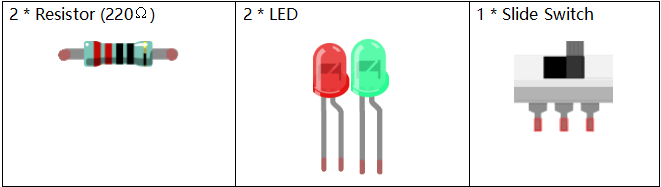
Newly Added Components
Principle
Slide Switch
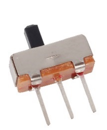
Just as its name suggests, slide switch is to connect or disconnect the circuit by sliding its switch handle so as to switch the circuit. The common types of slide switch include single pole double throw, single pole triple throw, double pole double throw, and double pole triple throw and so on. Generally, it is used in circuits with a low voltage and features flexibility and stabilization. Slide switches are commonly used in all kinds of instruments/meters equipment, electronic toys and other fields related.
How it works: The middle pin is fixed. When the handle is pushed to the left, the left two pins are connected; when push it to the right, the two pins on the right connect, thus switching circuits.
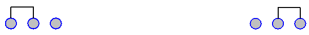
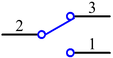
See the circuit symbol of slide switch and 2 is the middle pin.
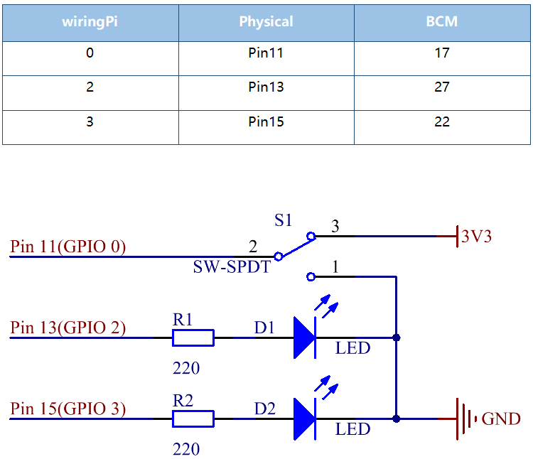
Schematic Diagram
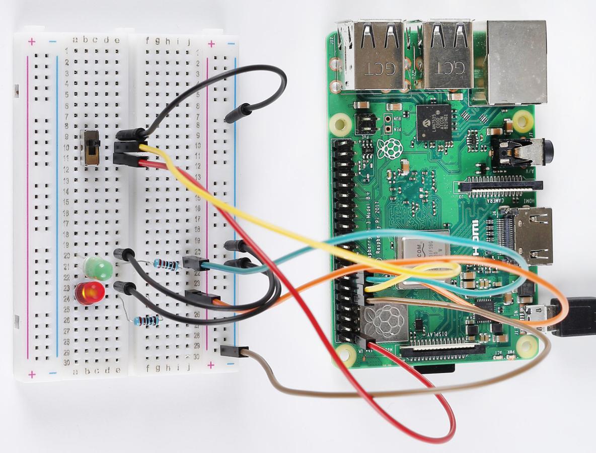
Here we use a slide switch to turn the LED on/off, which is simple. Connect the middle pin of the switch to pin 11. Connect the left pin of the switch to GND, the right to 3.3V. Attach the anode pins (the longer pins) of the two LEDs to pin 13 and pin 15 respectively after getting them connected with two 220Ω resistors. In addition, insert the cathodes of the two LEDs into GND. Get the slide switch connected to the left, the signal read on pin 11 is 0 (a low level), so the LED 1 lights up; to the right, the signal read on pin 11 is 1 (a high level), then the LED 2 turns on.
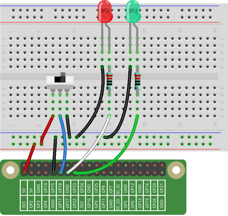
Build the Circuit
For C Language Users
Command
1. Go to the folder of the code.
cd /home/pi/electronic-kit/for-raspberry-pi/c/Lesson_7_SlideSwitch
2. Compile the code.
gcc 7_Slider.c -lwiringPi
3. Run the executable file.
sudo ./a.out
When the slide is pulled to the right, the LED2 is on and LED1 off. If the slide is pulled to the left, the LED1 is on and LED2 off.
Note
If it does not work after running, or there is an error prompt: "wiringPi.h: No such file or directory", please refer to C code is not working?.
Code
#include <wiringPi.h>
#include <stdio.h>

#define slidePin        0
#define led1            2
#define led2            3

int main(void)
{
    // When initialize wiring failed, print message to screen
    if(wiringPiSetup() == -1){
        printf("setup wiringPi failed !");
        return 1;
    }

    pinMode(slidePin, INPUT);
    pinMode(led1, OUTPUT);
    pinMode(led2, OUTPUT);

    while(1){
        // slide switch high, led1 on
        if(digitalRead(slidePin) == 1){
            digitalWrite(led1, HIGH);
            digitalWrite(led2, LOW);
            printf("LED1 on\n");
            delay(100);
        }
        // slide switch low, led2 on
        if(digitalRead(slidePin) == 0){
            digitalWrite(led2, HIGH);
            digitalWrite(led1, LOW);
            printf(".....LED2 on\n");
            delay(100);
        }
    }
    return 0;
}
Code Explanation
16.    pinMode(slidePin, INPUT);
17.    pinMode(led1, OUTPUT);
18.    pinMode(led2, OUTPUT);
Initialize the pins connected to slide switch to the INPUT mode, and initialize the LED lights to the OUTPUT mode.
22.        if(digitalRead(slidePin) == 1){
23.            digitalWrite(led1, HIGH);
24.            digitalWrite(led2, LOW);
25.            printf("LED1 on\n");
26.            delay(100);
27.        }
When the slide is pulled to the left, the middle pin and left one are connected; the Raspberry Pi reads a high level at the middle pin, so the LED1 is on and LED2 off.
28.        if(digitalRead(slidePin) == 0){
29.            digitalWrite(led2, HIGH);
30.            digitalWrite(led1, LOW);
31.            printf(".....LED2 on\n");
32.            delay(100);
33.        }
When the slide is pulled to the right, the middle pin and right one are connected; the Raspberry Pi reads a low, so the LED2 is on and LED1 off.
For Python Language Users
Command
Go to the folder of the code
cd /home/pi/electronic-kit/for-raspberry-pi/python
Run the code
sudo python3 7_Slider.py
When the slide is pulled to the right, the LED2 is on and LED1 off. If the slide is pulled to the left, the LED1 is on and LED2 off.
Code
Note
You can Modify/Reset/Copy/Run/Stop the code below. But before that, you need to go to source code path like electronic-kit/for-raspberry-pi/python. After modifying the code, you can run it directly to see the effect.
import RPi.GPIO as GPIO
import time

slidePin = 17
led1Pin = 27
led2Pin = 22

# Define a setup function for some setup
def setup():
    GPIO.setmode(GPIO.BCM)
    GPIO.setup(slidePin, GPIO.IN)
    GPIO.setup(led1Pin, GPIO.OUT, initial=GPIO.LOW)
    GPIO.setup(led2Pin, GPIO.OUT, initial=GPIO.LOW)

def main():
    while True:
        # slide switch high, led1 on
        if GPIO.input(slidePin) == 1:
            print ('LED1 ON ')
            GPIO.output(led2Pin, GPIO.LOW)
            GPIO.output(led1Pin, GPIO.HIGH)

        # slide switch low, led2 on
        if GPIO.input(slidePin) == 0:
            print ('    LED2 ON ')
            GPIO.output(led1Pin, GPIO.LOW)
            GPIO.output(led2Pin, GPIO.HIGH)
        time.sleep(0.5)

def destroy():
    # Turn off LED
    GPIO.output(led1Pin, GPIO.LOW)
    GPIO.output(led2Pin, GPIO.LOW)
    # Release resource
    GPIO.cleanup()

# If run this script directly, do:
if __name__ == '__main__':
    setup()
    try:
        main()
    # When 'Ctrl+C' is pressed, the child program
    # destroy() will be  executed.
    except KeyboardInterrupt:
        destroy()
Code Explanation
11.    GPIO.setup(slidePin, GPIO.IN)
12.    GPIO.setup(led1Pin, GPIO.OUT, initial=GPIO.LOW)
13.    GPIO.setup(led2Pin, GPIO.OUT, initial=GPIO.LOW)
Initialize the pin, then set the pin connected to slide switch to the input mode and LEDs to the output mode.
18.    if GPIO.input(slidePin) == 1:
19.            GPIO.output(led2Pin, GPIO.LOW)
20.            GPIO.output(led1Pin, GPIO.HIGH)
When the slide is pulled to the left, the middle pin and left one are connected; the Raspberry Pi reads a high level at the middle pin, so the LED1 is on and LED2 off.
24.       if GPIO.input(slidePin) == 0:
25.            GPIO.output(led1Pin, GPIO.LOW)
26.            GPIO.output(led2Pin, GPIO.HIGH)
When the slide is pulled to the right, the middle pin and right one are connected; the Raspberry Pi reads a low, so the LED2 is on and LED1 off.
Phenomenon Picture