Note
Hello, welcome to the SunFounder Raspberry Pi & Arduino & ESP32 Enthusiasts Community on Facebook! Dive deeper into Raspberry Pi, Arduino, and ESP32 with fellow enthusiasts.
Why Join?
Expert Support: Solve post-sale issues and technical challenges with help from our community and team.
Learn & Share: Exchange tips and tutorials to enhance your skills.
Exclusive Previews: Get early access to new product announcements and sneak peeks.
Special Discounts: Enjoy exclusive discounts on our newest products.
Festive Promotions and Giveaways: Take part in giveaways and holiday promotions.
👉 Ready to explore and create with us? Click [here] and join today!
Lesson 16 Servo
Introduction
Servo is a type of geared motor that can only rotate 180 degrees. It is controlled by sending electrical pulses from your board. These pulses tell the servo what position it should move to.
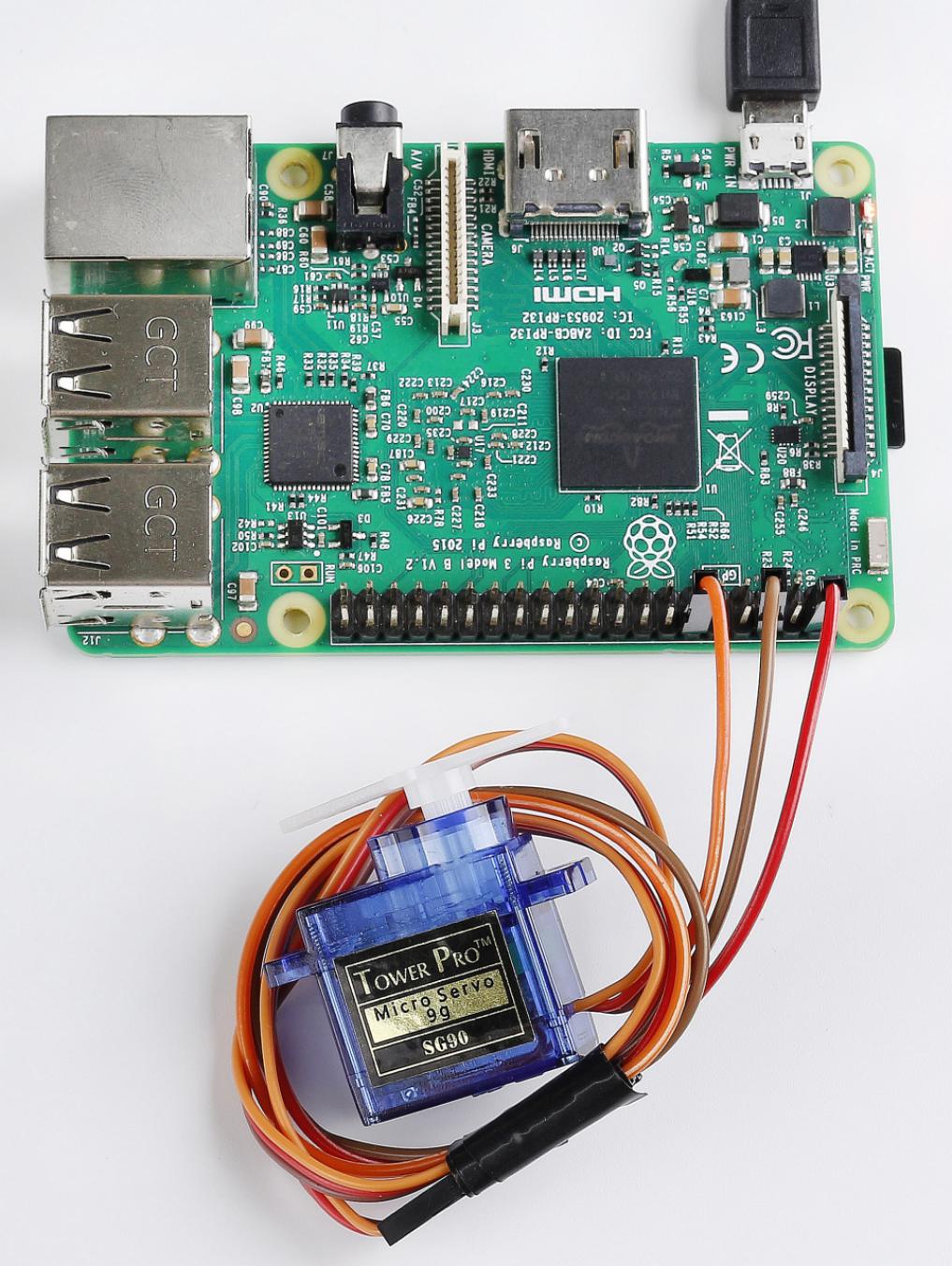
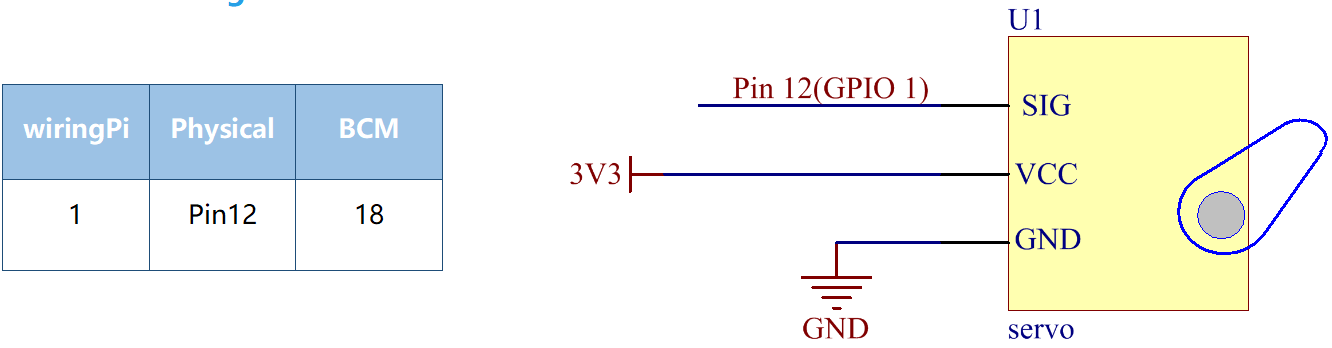
A servo has three wires: the brown wire is GND, the red one is VCC, and the orange one is signal line.
Newly Added Components
Principle
Servo
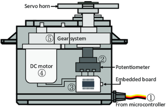
A servo is generally composed of the following parts: case, shaft, gear system, potentiometer, DC motor, and embedded board.
It works like this: The microcontroller sends out PWM signals to the servo, and then the embedded board in the servo receives the signals through the signal pin and controls the motor inside to turn. As a result, the motor drives the gear system and then motivates the shaft after deceleration. The shaft and potentiometer of the servo are connected together. When the shaft rotates, it drives the potentiometer, so the potentiometer outputs a voltage signal to the embedded board. Then the board determines the direction and speed of rotation based on the current position, so it can stop exactly at the right position as defined and hold there.
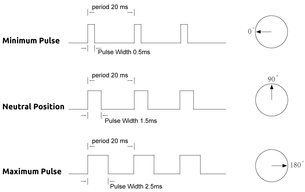
The angle is determined by the duration of a pulse that is applied to the control wire. This is called Pulse width Modulation. The servo expects to see a pulse every 20 ms. The length of the pulse will determine how far the motor turns. For example, a 1.5ms pulse will make the motor turn to the 90 degree position (neutral position).
When a pulse is sent to a servo that is less than 1.5 ms, the servo rotates to a position and holds its output shaft some number of degrees counterclockwise from the neutral point. When the pulse is wider than 1.5 ms the opposite occurs. The minimal width and the maximum width of pulse that will command the servo to turn to a valid position are functions of each servo. Generally the minimum pulse will be about 0.5 ms wide and the maximum pulse will be 2.5 ms wide.
Schematic Diagram
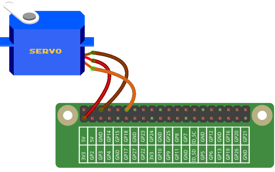
Build the Circuit
Note: Connect the brown to GND, Red to VCC, Orange to pin12 of the control board.
For C Language Users
Command
1. Go to the folder of the code.
cd /home/pi/electronic-kit/for-raspberry-pi/c/Lesson_16_Servo
2. Compile the code.
gcc 16_Servo.c -lwiringPi
3. Run the executable file.
sudo ./a.out
After the program is executed, the servo will rotate from 0 degrees to 180 degrees, and then from 180 degrees to 0 degrees, circularly.
Note
If it does not work after running, or there is an error prompt: "wiringPi.h: No such file or directory", please refer to C code is not working?.
Code
#include <wiringPi.h>
#include <softPwm.h>
#include <stdio.h>

#define ServoPin    1
long Map(long value,long fromLow,long fromHigh,long toLow,long toHigh){
    return (toHigh-toLow)*(value-fromLow) / (fromHigh-fromLow) + toLow;
}
void setAngle(int pin, int angle){    //Specif a certain rotation angle (0-180) for the servo
    if(angle < 0)
        angle = 0;
    if(angle > 180)
        angle = 180;
    softPwmWrite(pin,map(angle,0,180,5,25));
}

int main(void)
{
    int i;

    if(wiringPiSetup() == -1){ //when initialize wiring faiservo,print message to screen
        printf("setup wiringPi failed !");
        return 1;
    }
    softPwmCreate(servoPin,  0, 200);       //initialize PMW pin of servo
    while(1){
        for(i=0;i<181;i++){
            setAngle(ServoPin,i);
            delay(1);
        }
        delay(500);
        for(i=181;i>-1;i--){
            setAngle(ServoPin,i);
            delay(1);
        }
        delay(500);
    }
    return 0;
}
Code Explanation
6.long Map(long value,long fromLow,long fromHigh,long toLow,long toHigh){
7.    return (toHigh-toLow)*(value-fromLow) / (fromHigh-fromLow) + toLow;
8.}
Create a map() function to map value in the following code.
9.void setAngle(int pin, int angle){    //Specif a certain rotation angle (0-180) for the servo
10.    if(angle < 0)
11.        angle = 0;
12.    if(angle > 180)
13.        angle = 180;
14.    softPwmWrite(pin,map(angle,0,180,5,25));
15.}
Define a function to limit the angle of the servo to 0 to 180 in order to set the angle of servo.
softPwmWrite(pin,map(angle,0,180,5,25));
This function can change the duty cycle of the PWM pin.
To make the servo rotate to 0 ~ 180 °, the pulse width should change within the range of 0.5ms ~ 2.5ms when the period is 20ms; in the function, softPwmCreate(), we have set that the period is 200x100us=20ms, thus we need to map 0 ~ 180 to 5x100us ~ 25x100us.
25. softPwmCreate(ServoPin, 0, 200);
The function is to use softwares to create a PWM pin, servoPin, then the initial pulse widths of them are set to 0, and the period of PWM is 200 x100us.
27.        for(i=0;i<181;i++){
28.            setAngle(ServoPin,i);
29.            delay(1);
30.        }
In a for loop, we want servo to rotate from 0 degrees to 180 degrees.
32.        for(i=181;i>-1;i--){
33.            setAngle(ServoPin,i);
34.            delay(1);
35.        }
In a for loop, we want servo to rotate from 180 degrees to 0 degrees.
For Python Language Users
Command
1. Go to the folder of the code.
cd /home/pi/electronic-kit/for-raspberry-pi/python
2. Run the code.
sudo python3 16_Servo.py
After the program is executed, the servo will rotate from 0 degrees to 180 degrees, and then from 180 degrees to 0 degrees, circularly.
Code
Note
You can Modify/Reset/Copy/Run/Stop the code below. But before that, you need to go to source code path like electronic-kit/for-raspberry-pi/python. After modifying the code, you can run it directly to see the effect.
import RPi.GPIO as GPIO
import time

SERVO_MIN_PULSE = 500
SERVO_MAX_PULSE = 2500

ServoPin = 18

def map(value, inMin, inMax, outMin, outMax):
    return (outMax - outMin) * (value - inMin) / (inMax - inMin) + outMin

def setup():
    global p
    GPIO.setmode(GPIO.BCM)       # Numbers GPIOs by BCM
    GPIO.setup(ServoPin, GPIO.OUT)   # Set ServoPin's mode is output
    GPIO.output(ServoPin, GPIO.LOW)  # Set ServoPin to low
    p = GPIO.PWM(ServoPin, 50)     # set Frequecy to 50Hz
    p.start(0)                     # Duty Cycle = 0

def setAngle(angle):      # make the servo rotate to specific angle (0-180 degrees)
    angle = max(0, min(180, angle))
    pulse_width = map(angle, 0, 180, SERVO_MIN_PULSE, SERVO_MAX_PULSE)
    pwm = map(pulse_width, 0, 20000, 0, 100)
    p.ChangeDutyCycle(pwm)#map the angle to duty cycle and output it

def loop():
    while True:
        for i in range(0, 181, 5):   #make servo rotate from 0 to 180 deg
            setAngle(i)     # Write to servo
            time.sleep(0.002)
        time.sleep(1)
        for i in range(180, -1, -5): #make servo rotate from 180 to 0 deg
            setAngle(i)
            time.sleep(0.001)
        time.sleep(1)

def destroy():
    p.stop()
    GPIO.cleanup()

if __name__ == '__main__':     #Program start from here
    setup()
    try:
        loop()
    except KeyboardInterrupt:  # When 'Ctrl+C' is pressed, the program destroy() will be executed.
        destroy()
Code Explanation
9.def map(value, inMin, inMax, outMin, outMax):
10.    return (outMax - outMin) * (value - inMin) / (inMax - inMin) + outMin
Create a map() function to map value in the following code.
17.  p = GPIO.PWM(ServoPin, 50)
18.  p.start(0)
Set the servoPin to PWM pin, then the frequency to 50 hz, and the period to 20ms. p.start(0): Run the PWM function,and set the initial value to 0.
20.def setAngle(angle):      # make the servo rotate to specific angle (0-180 degrees)
21.    angle = max(0, min(180, angle))
22.    pulse_width = map(angle, 0, 180, SERVO_MIN_PULSE, SERVO_MAX_PULSE)
23.    pwm = map(pulse_width, 0, 20000, 0, 100)
24.    p.ChangeDutyCycle(pwm)#map the angle to duty cycle and output it
Create a function, setAngle() to write angle that ranges from 0 to 180 into the servo.
24.p.ChangeDutyCycle(pwm)
This function can change the duty cycle of the PWM. To render a range 0 ~ 180° to the servo, the pulse width of the servo is set to 0.5ms-2.5ms.
In the previous codes, the period of PWM was set to 20ms, thus the duty cycle of PWM is (0.5/20)%-(2.5/20)%, and the range 0 ~ 180 is mapped to 2.5 ~ 12.5.
28.        for i in range(0, 181, 5):   #make servo rotate from 0 to 180 deg
29.            setAngle(i)     # Write to servo
30.            time.sleep(0.002)
In a for loop, we want servo to rotate from 0 degrees to 180 degrees.
32.        for i in range(180, -1, -5): #make servo rotate from 180 to 0 deg
33.            setAngle(i)
34.            time.sleep(0.001)
In a for loop, we want servo to rotate from 180 degrees to 0 degrees.
Phenomenon Picture