Note
Hello, welcome to the SunFounder Raspberry Pi & Arduino & ESP32 Enthusiasts Community on Facebook! Dive deeper into Raspberry Pi, Arduino, and ESP32 with fellow enthusiasts.
Why Join?
Expert Support: Solve post-sale issues and technical challenges with help from our community and team.
Learn & Share: Exchange tips and tutorials to enhance your skills.
Exclusive Previews: Get early access to new product announcements and sneak peeks.
Special Discounts: Enjoy exclusive discounts on our newest products.
Festive Promotions and Giveaways: Take part in giveaways and holiday promotions.
👉 Ready to explore and create with us? Click [here] and join today!
19. Reverse Parking Alarm System

When reversing a car, it is crucial to be aware of obstacles behind the vehicle, especially in situations with limited visibility. To enhance safety, many modern vehicles are equipped with reverse warning systems.
In this project, we will use an Arduino, an ultrasonic sensor, and an active buzzer to simulate such a system. The ultrasonic sensor helps detect the distance to obstacles behind the vehicle, and when this distance is too short, the active buzzer will sound an alert to warn the driver.
This project not only allows us to better understand how ultrasonic sensors work but also teaches us how to program and control using Arduino to implement a practical reverse warning function.
Ultrasonic Module
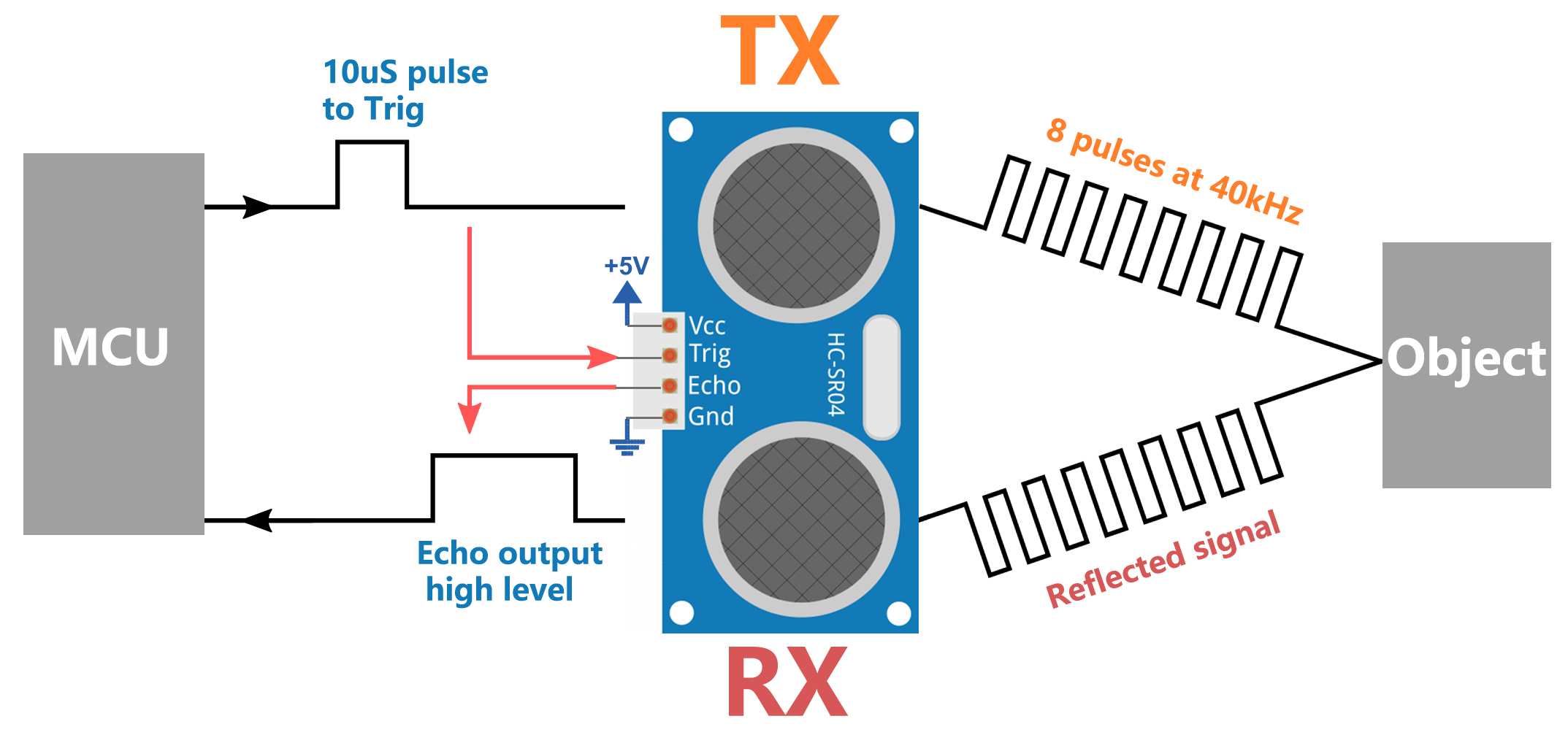
Imagine you are in a dark room and can’t see the objects around you. In this situation, you could clap your hands to produce a sound that travels outward. When this sound hits a wall or another object, it bounces back as an echo. If you listen carefully, you can hear this echo. By calculating the time it takes for the sound to travel out and the echo to return, you can roughly estimate how far away the wall or object is. Ultrasonic sensors work in a similar way to “see” the world around them.
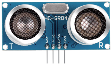
Ultrasonic sensors mainly consist of two parts: a transmitter and a receiver, much like your mouth and ears.
Emitting Sound Waves:
When the ultrasonic sensor is activated, the transmitter emits a series of rapid sound waves, similar to clapping your hands. These sound waves have such a high frequency that our ears cannot hear them.
Sound Travels and Returns:
The sound waves propagate forward until they hit something like a wall or a table, and then they bounce back.
Receiving Sound Waves:
The receiver part of the ultrasonic sensor is responsible for “listening” to these echoes, just like your ears catching the sound waves reflected back from objects.
Calculating Distance:
The sensor records the time it takes for the sound waves to travel out and back. Since the speed of sound is known (about 340 meters per second in air), multiplying this time by the speed of sound gives the total distance the sound waves traveled. Since we only need the one-way distance to the object, we divide the total distance by 2 to get the final result. This technology makes ultrasonic sensors very useful in many situations, such as helping robots avoid obstacles or assisting drivers by indicating the distance to objects behind a vehicle when reversing.
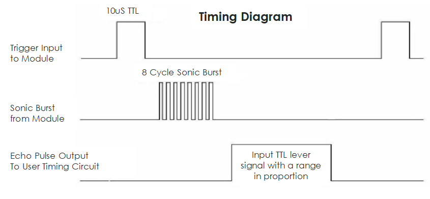
Ultrasonic Timing
The timing diagram is shown below. You only need to supply a short 10us pulse for the trigger input to start the ranging, and then the module will send out an 8 cycle burst of ultrasound at 40 kHz and raise its echo. You can calculate the range through the time interval between sending trigger signal and receiving echo signal.
Formula: us / 58 = centimeters or us / 148 =inch; or: the range = high level time * velocity (340M/S) / 2; you are suggested to use measurement cycle over 60ms in order to prevent signal collisions of trigger signal and the echo signal.
Building the Circuit
Components Needed
1 * Arduino Uno R3 |
1 * Ultrasonic Module |
1 * Active Buzzer |
Jumper Wires |
|
|
|
|
1 * USB Cable |
1 * Breadboard |
1 * Multimeter |
|
|
|
|


Building Step-by-Step
Follow the wiring diagram, or the steps below to build your circuit.

Code Creation
Open the Arduino IDE and start a new project by selecting “New Sketch” from the “File” menu.
Save your sketch as
Lesson19_reversin_alarmusingCtrl + Sor by clicking “Save”.Firstly, we need to define the pins on the Arduino that are connected to the ultrasonic sensor and the buzzer. This step is crucial as it sets the foundation for the hardware interface.
TRIGGER_PIN and ECHO_PIN are used for triggering and receiving echoes from the ultrasonic sensor.
BUZZER_PIN is the pin connected to the buzzer.
#define TRIGGER_PIN  10
#define ECHO_PIN     9
#define BUZZER_PIN   2
In the setup() function, we set the mode for each pin. The Trig pin needs to be set to output (as it sends the signal), the Echo pin is set to input (as it receives the signal), and the buzzer pin is also set to output (as it needs to emit sound).
void setup() {
  pinMode(TRIGGER_PIN, OUTPUT);
  pinMode(ECHO_PIN, INPUT);
  pinMode(BUZZER_PIN, OUTPUT);
  Serial.begin(9600); // Start serial communication for debugging and distance viewing
}
Writing the measureDistance() Function:
The measureDistance() function encapsulates the logic required to trigger the ultrasonic sensor and read the distance based on the echo received:
Triggering the Ultrasonic Pulse
Set the TRIGGER_PIN low initially to ensure a clean pulse.
A short delay of 2 microseconds ensures the line is clear.
Send a 10-microsecond high pulse to the TRIGGER_PIN. This pulse tells the sensor to emit an ultrasonic sound wave.
Set the TRIGGER_PIN back to low to end the pulse.
long measureDistance() {
  digitalWrite(TRIGGER_PIN, LOW);  // Ensure Trig pin is low before a pulse
  delayMicroseconds(2);
  digitalWrite(TRIGGER_PIN, HIGH); // Send a high pulse
  delayMicroseconds(10);           // Pulse duration of 10 microseconds
  digitalWrite(TRIGGER_PIN, LOW);  // End the high pulse
}
Note
In previous lessons, we worked with int and float types of variables or constants. Now, let’s understand what long and unsigned long variables are about:
long: Alonginteger is an extended version of anint. It is used to store larger integer values that exceed the capacity of standardint. A long typically occupies 32 or 64 bits of memory, which allows it to hold much larger values, both positive and negative.unsigned long: Anunsigned longis similar to alongbut can only represent non-negative values. It uses the bit normally reserved for the sign to extend the range of possible values it can hold, but strictly in the positive spectrum.
Reading the Echo
The pulseIn() function is used on the ECHO_PIN to measure the duration of the incoming pulse. This function waits for the pin to go HIGH, times how long it stays HIGH, and then returns the duration in microseconds.
This duration is the time taken for the ultrasonic pulse to travel to the object and back.
long measureDistance() {
  digitalWrite(TRIGGER_PIN, LOW);  // Ensure Trig pin is low before a pulse
  delayMicroseconds(2);
  digitalWrite(TRIGGER_PIN, HIGH); // Send a high pulse
  delayMicroseconds(10);           // Pulse duration of 10 microseconds
  digitalWrite(TRIGGER_PIN, LOW);  // End the high pulse
  long duration = pulseIn(ECHO_PIN, HIGH);  // Measure the duration of high level on Echo pin
}
Calculating the Distance
The speed of sound in air (approximately 340 m/s) is used here. The formula to calculate the distance is (duration * speed of sound) / 2. We divide by 2 because the sound wave travels to the object and back, so we only need half the distance for a one-way measurement.
In our code, 0.034 cm/us (speed of sound in cm/microsecond) is used as a conversion factor.
long measureDistance() {
  digitalWrite(TRIGGER_PIN, LOW);  // Ensure Trig pin is low before a pulse
  delayMicroseconds(2);
  digitalWrite(TRIGGER_PIN, HIGH); // Send a high pulse
  delayMicroseconds(10);           // Pulse duration of 10 microseconds
  digitalWrite(TRIGGER_PIN, LOW);  // End the high pulse
  long duration = pulseIn(ECHO_PIN, HIGH);  // Measure the duration of high level on Echo pin
  long distance = duration * 0.034 / 2;     // Calculate the distance (in cm)
  return distance;
}
6. Implement the Main Loop In the loop() function, the distance is measured frequently using the measureDistance() function. Decisions are made based on this distance, such as whether to activate the buzzer.
void loop() {
  long distance = measureDistance(); // Measure distance
  Serial.print("Distance: ");
  Serial.print(distance);
  Serial.println(" cm");

  if (distance > 0 && distance <= 50) {
    digitalWrite(BUZZER_PIN, HIGH);  // Activate the buzzer if close
    delay(100);                      // Buzzer sounds for 100 milliseconds
    digitalWrite(BUZZER_PIN, LOW);   // Turn off the buzzer
  } else {
    digitalWrite(BUZZER_PIN, LOW);   // Keep the buzzer off
  }

  delay(100);  // Delay between measurements to prevent sensor overload
}
Here is your complete code. You can now click “Upload” to upload the code to the Arduino Uno R3.
#define TRIGGER_PIN  10
#define ECHO_PIN     9
#define BUZZER_PIN   2

void setup() {
  pinMode(TRIGGER_PIN, OUTPUT);  // Set the Trig pin as output
  pinMode(ECHO_PIN, INPUT);      // Set the Echo pin as input
  pinMode(BUZZER_PIN, OUTPUT);   // Set the buzzer pin as output
  Serial.begin(9600);            // Start serial communication for debugging
}

void loop() {
  long distance = measureDistance(); // Call the function to measure distance
  Serial.print("Distance: ");
  Serial.print(distance);
  Serial.println(" cm");

  if (distance > 0 && distance <= 50) { // If distance is within 50 centimeters
    digitalWrite(BUZZER_PIN, HIGH);     // Turn on the buzzer
    delay(100);                         // Buzzer sounds for 100 milliseconds
    digitalWrite(BUZZER_PIN, LOW);      // Turn off the buzzer
  } else {
    digitalWrite(BUZZER_PIN, LOW);      // Keep the buzzer off
  }

  delay(100);  // Delay between measurements
}

long measureDistance() {
  digitalWrite(TRIGGER_PIN, LOW);  // Ensure Trig pin is low before a pulse
  delayMicroseconds(2);
  digitalWrite(TRIGGER_PIN, HIGH); // Send a high pulse
  delayMicroseconds(10);           // Pulse duration of 10 microseconds
  digitalWrite(TRIGGER_PIN, LOW);  // End the high pulse

  long duration = pulseIn(ECHO_PIN, HIGH);  // Measure the duration of high level on Echo pin
  long distance = duration * 0.034 / 2;     // Calculate the distance (in cm)
  return distance;
}
Finally, remember to save your code and tidy up your workspace.
Question
If you want the distance detected by this device to be more accurate to decimals, how should you modify the code?