Note
Hello, welcome to the SunFounder Raspberry Pi & Arduino & ESP32 Enthusiasts Community on Facebook! Dive deeper into Raspberry Pi, Arduino, and ESP32 with fellow enthusiasts.
Why Join?
Expert Support: Solve post-sale issues and technical challenges with help from our community and team.
Learn & Share: Exchange tips and tutorials to enhance your skills.
Exclusive Previews: Get early access to new product announcements and sneak peeks.
Special Discounts: Enjoy exclusive discounts on our newest products.
Festive Promotions and Giveaways: Take part in giveaways and holiday promotions.
👉 Ready to explore and create with us? Click [here] and join today!
13. The Spectrum of Sight
Welcome to this lesson, where we unravel the mystery of human color perception and replicate it using technology. In this lesson, we delve into how our eyes distinguish millions of colors and how this incredible ability can be simulated digitally with RGB LEDs. By exploring the interplay of photoreceptors in our eyes and the RGB color model, you’ll learn to recreate the vividness of the world in digital form.
Overview
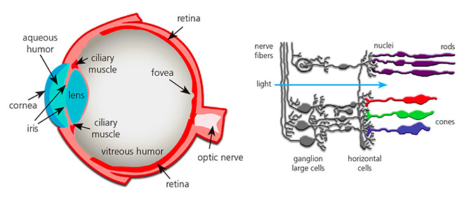
The human visual system can perceive about ten million different colors, a capability achieved through photoreceptor cells in the retina—cones and rods. Perception of color is not linear; our visual system is more sensitive to changes in certain colors than others. Cones, which are sensitive to color, primarily come in three types, each most sensitive to either red, green, or blue light.
The human eye perceives about ten million different colors, thanks to specialized cells in the retina called cones and rods. This perception isn’t uniform across the spectrum; we’re more sensitive to changes in some colors than others. Cones, which detect color, are predominantly sensitive to red, green, or blue wavelengths.
The RGB color model is an additive color model where colors are created by mixing varying intensities of red, green, and blue light. In this model, red, green, and blue are typically considered primary color channels. By adjusting the intensity of each channel (from 0 to a maximum value, typically 255 corresponding to an 8-bit color depth), it is possible to produce a visible spectrum of over 16 million different colors. For instance, orange can be achieved by mixing more red with less green.
The RGB color model uses an additive approach, mixing red, green, and blue light to create a broad array of colors. This model reflects how our visual system combines light from different parts of the spectrum to form diverse hues. By manipulating the intensity of these three primary colors, we can generate over 16 million distinct colors. For example, by increasing red and decreasing green, we achieve orange.

In this interactive lesson, you will apply these principles to control an RGB LED, enabling it to display colors of your choice through precise electronic commands.
Learning Objectives
Grasp how this model mimics human color perception and its application in digital displays.
Learn to use Pulse Width Modulation (PWM) for nuanced color mixing with RGB LED.
Enhance your coding efficiency and clarity by creating functions that take parameters in Arduino.
Experiment with different RGB values to customize colors on your LED, mirroring the complexity of human color vision.
Building the Circuit
Components Needed
1 * Arduino Uno R3 |
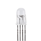
1 * RGB LED |
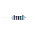
3 * 220Ω Resistor |
Jumper Wires |
|
|
|
|
1 * USB Cable |
1 * Breadboard |
||
|
|


This lesson uses the same circuit as Lesson 12.

Code Creation - Displaying Colors
In our journey to master the control of RGB LEDs, we’ve seen how using digitalWrite() can light up the LED in basic colors. To further explore and unlock the full spectrum of colors that an RGB LED can produce, we’ll now delve into using analogWrite() to send PWM (Pulse Width Modulation) signals, allowing us to achieve a wide range of hues.
Let’s see how we can implement this with code.
Open the Arduino IDE and start a new project by selecting “New Sketch” from the “File” menu.
Save your sketch as
Lesson13_PWM_Color_MixingusingCtrl + Sor by clicking “Save”.First, set the three pins of the RGB LED as outputs:
void setup() {
    // Set up code to run once:
    pinMode(9, OUTPUT);   // Set Blue pin of RGB LED as output
    pinMode(10, OUTPUT);  // Set Green pin of RGB LED as output
    pinMode(11, OUTPUT);  // Set Red pin of RGB LED as output
}
Use
analogWrite()to send PWM values to the RGB LED. From Lesson 9, we know that PWM values can change an LED’s brightness, and the PWM range is 0-255. To display red, we set the PWM value of the RGB LED’s red pin to 255, and the other two pins to 0.
void setup() {
    // Set up code to run once:
    pinMode(9, OUTPUT);   // Set Blue pin of RGB LED as output
    pinMode(10, OUTPUT);  // Set Green pin of RGB LED as output
    pinMode(11, OUTPUT);  // Set Red pin of RGB LED as output
}

void loop() {
    // Main code to run repeatedly:
    analogWrite(9, 0);    // Set the PWM value of Blue pin to 0
    analogWrite(10, 0);   // Set the PWM value of Green pin to 0
    analogWrite(11, 255);  // Set the PWM value of Red pin to 255
}
With this setup, after uploading the code to the Arduino Uno R3, you will see the RGB LED display red.
The
analogWrite()function allows the RGB LED to display not only the seven basic colors but many other different hues. Now you can adjust the values of pins 9, 10, and 11 separately, and record the observed colors in your handbook.
Red Pin |
Green Pin |
Blue Pin |
Color |
|---|---|---|---|
0 |
128 |
128 |
|
128 |
0 |
255 |
|
128 |
128 |
255 |
|
255 |
128 |
0 |
Code Creation - Parameterized Functions
Using the analogWrite() function to display different colors can make your code lengthy if you want to display many colors simultaneously. Therefore, we need to create functions.
Unlike the previous lesson, we are preparing to create a function with parameters.
A parameterized function allows you to pass specific values into the function, which can then use these values to perform its tasks. This is incredibly useful for adjusting properties like color intensity on the fly. It makes your code more flexible and easier to read.
When defining a parameterized function, you specify what values it needs to operate through parameters listed in parentheses right after the function name. These parameters act like placeholders that get replaced by actual values when the function is called.
Here’s how to define a parameterized function for setting the color of an RGB LED:
Open the sketch you saved earlier,
Lesson13_PWM_Color_Mixing.Hit “Save As…” from the “File” menu, and rename it to
Lesson13_PWM_Color_Mixing_Function. Click “Save”.Start by declaring the function after the
void loop()with the keywordvoid, followed by the function name and parameters in parentheses. For oursetColorfunction, we’ll use three parameters—red,green, andblue—each representing the intensity of the corresponding color component of the RGB LED.
void loop() {
    // put your main code here, to run repeatedly:
}

void setColor(int red, int green, int blue) {
}
Within the function body, use the
analogWrite()command to send PWM signals to the RGB LED pins. The values passed tosetColorwill determine the brightness of each color. The parametersred,green, andblueare used here to directly control the intensity of each LED pin.
// Function to set the color of the RGB LED
void setColor(int red, int green, int blue) {
    // Write PWM value for red, green, and blue to the RGB LED
    analogWrite(11, red);
    analogWrite(10, green);
    analogWrite(9, blue);
}
Now you can call your newly created
setColor()function in thevoid loop(). Since you created a function with parameters, you need to fill in the arguments in the()such as(255, 0, 0). Remember to write comments.
void loop() {
    // put your main code here, to run repeatedly:
    setColor(255, 0, 0); // Display red color
}

// Function to set the color of the RGB LED
void setColor(int red, int green, int blue) {
    // Write PWM value for red, green, and blue to the RGB LED
    analogWrite(11, red);
    analogWrite(10, green);
    analogWrite(9, blue);
}
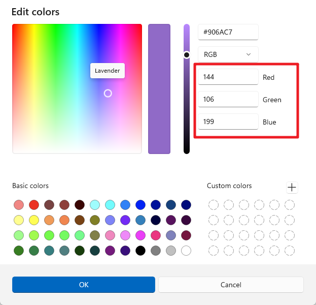
We already know that by providing different values to the three pins of the RGB LED, we can light up different colors of light. So, how do we make the RGB LED light up exactly the color we want? This requires the aid of a color palette. Open Paint (this software comes with Windows) or any drawing software on your personal computer.
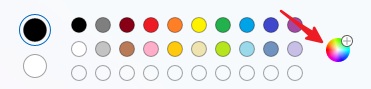
Choose a color you like, record its RGB values.
Note
Note that before you select a color, adjust the lumens to the proper position.
Fill in the color you selected into the
setColor()function in thevoid loop(), use thedelay()function to specify the display time for each color.
void loop() {
    // put your main code here, to run repeatedly:
    setColor(255, 0, 0);      // Display red color
    delay(1000);              // Wait for 1 second
    setColor(0, 128, 128);    // Display teal color
    delay(1000);              // Wait for 1 second
    setColor(128, 0, 255);    // Display purple color
    delay(1000);              // Wait for 1 second
    setColor(128, 128, 255);  // Display Light blue color
    delay(1000);              // Wait for 1 second
    setColor(255, 128, 0);    // Display orange color
    delay(1000);              // Wait for 1 second
}
Below is the complete code; you can click “Upload” to upload the code to the Arduino Uno R3 to see the effects.
void setup() {
    // put your setup code here, to run once:
    pinMode(9, OUTPUT);   // Set Blue pin of RGB LED as output
    pinMode(10, OUTPUT);  // Set Green pin of RGB LED as output
    pinMode(11, OUTPUT);  // Set Red pin of RGB LED as output
}

void loop() {
    // put your main code here, to run repeatedly:
    setColor(255, 0, 0);      // Display red color
    delay(1000);              // Wait for 1 second
    setColor(0, 128, 128);    // Display teal color
    delay(1000);              // Wait for 1 second
    setColor(128, 0, 255);    // Display purple color
    delay(1000);              // Wait for 1 second
    setColor(128, 128, 255);  // Display Light blue color
    delay(1000);              // Wait for 1 second
    setColor(255, 128, 0);    // Display orange color
    delay(1000);              // Wait for 1 second
}

// Function to set the color of the RGB LED
void setColor(int red, int green, int blue) {
    // Write PWM value for red, green, and blue to the RGB LED
    analogWrite(11, red);
    analogWrite(10, green);
    analogWrite(9, blue);
}
Finally, remember to save your code and tidy up your workspace.
Summary
Today’s exploration of color perception bridges the gap between biological science and electronic application, highlighting the power of programming in bringing abstract concepts to life. By adjusting RGB values on an LED, you’ve mimicked the eye’s method of perceiving color, gaining both a deeper appreciation for human biology and advanced skills in electronic control.