Note
Hello, welcome to the SunFounder Raspberry Pi & Arduino & ESP32 Enthusiasts Community on Facebook! Dive deeper into Raspberry Pi, Arduino, and ESP32 with fellow enthusiasts.
Why Join?
Expert Support: Solve post-sale issues and technical challenges with help from our community and team.
Learn & Share: Exchange tips and tutorials to enhance your skills.
Exclusive Previews: Get early access to new product announcements and sneak peeks.
Special Discounts: Enjoy exclusive discounts on our newest products.
Festive Promotions and Giveaways: Take part in giveaways and holiday promotions.
👉 Ready to explore and create with us? Click [here] and join today!
12. The Colors of the Rainbow
Imagine if you could paint with light, blending red, green, and blue to create every hue imaginable—just like mixing paints on a palette but with beams of light.
Welcome to this lesson, where you will explore the captivating world of RGB LEDs and discover how the combination of primary colors can create a vibrant spectrum of hues. This hands-on course will guide you through the principles of RGB LED functionality and introduce you to the practical applications of programming and circuit building.
In this lesson, you will learn:
Understand the operational principles of RGB LEDs.
Learn to create and utilize functions in your code to simplify tasks and enhance readability.
Explore the impact of different color combinations by manipulating the RGB LED.
Building the Circuit
Components Needed
1 * Arduino Uno R3 |
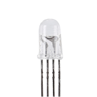
1 * RGB LED |
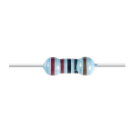
3 * 220Ω Resistor |
Jumper Wires |
|
|
|
|
1 * USB Cable |
1 * Breadboard |
1 * Multimeter |
|
|
|
|


Step-by-Step Building Instructions
Follow the wiring diagram or these steps to construct the circuit.

Start with an RGB LED.
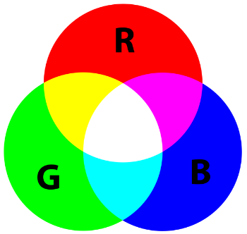
RGB LEDs emit light in various colors by integrating red, green, and blue LEDs within a single package. By varying the voltage input on the three pins, these LEDs can combine to produce up to 16,777,216 different colors.

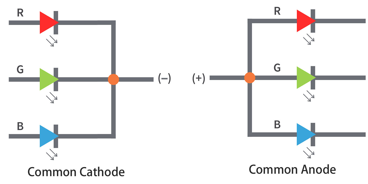
Depending on their design, RGB LEDs can be either common anode or common cathode. For this project, we use a common cathode RGB LED, where all three LEDs share a negative connection.
Common cathode RGB LEDs have a shared negative connection.
Common anode RGB LEDs have a shared positive connection.
An RGB LED typically has 4 pins; the longest one is the ground. When placing the RGB LED, ensure the longest lead is second from the left, configuring the pins as Red, GND, Green, and Blue from left to right.
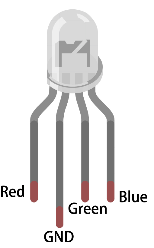
You can also use a multimeter in Diode Test mode to identify the color each pin emits.
Set the multimeter to the Continuity setting for resistance measurement.

Touch the black lead of the multimeter to the RGB LED’s longest pin, and touch the red lead to the other pins individually. You will see the RGB LED light up in red, green, or blue accordingly.

Insert the RGB LED into the breadboard with the longest pin going into hole 17D, and the other three pins into 18C, 16C, and 15C, respectively.
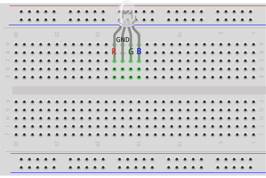
Insert three 220ohm resistors as shown from holes 15E to 15G, 16E to 16G, and 18E to 18G.

Connect these resistors to pins 9, 10, and 11 on the Arduino Uno R3 with jumper wires as illustrated.

Connect the longest pin of the RGB LED to GND using a jumper wire.
Code Creation - Lighting Up an RGB LED
Open the Arduino IDE and start a new project by selecting “New Sketch” from the “File” menu.
Save your sketch as
Lesson12_Rainbow_ColorusingCtrl + Sor by clicking “Save”.The LED in your circuit is connected to digital pins on the Arduino Uno R3. As the LED is an output device, you’ll need to set digital pins 9, 10, and 11 as
OUTPUT.
void setup() {
    // put your setup code here, to run once:
    pinMode(9, OUTPUT);   // Set Blue pin of RGB LED as output
    pinMode(10, OUTPUT);  // Set Green pin of RGB LED as output
    pinMode(11, OUTPUT);  // Set Red pin of RGB LED as output
}

void loop() {
    // put your main code here, to run repeatedly:
}
Now in the
void loop()set the RGB LED’s red pin toHIGH, and the other two pins toLOW.
Note
Since we are using PWM pins 9, 10, and 11, you have the option to use either digitalWrite() or analogWrite() to output a high or low level.
For this lesson, as we are simply setting the pins to high or low, we’ll use digitalWrite().
void setup() {
    // put your setup code here, to run once:
    pinMode(9, OUTPUT);   // Set Blue pin of RGB LED as output
    pinMode(10, OUTPUT);  // Set Green pin of RGB LED as output
    pinMode(11, OUTPUT);  // Set Red pin of RGB LED as output
}

void loop() {
    // put your main code here, to run repeatedly:
    digitalWrite(9, LOW);    // Turn off the Blue pin of RGB LED
    digitalWrite(10, LOW);   // Turn off the Green pin of RGB LED
    digitalWrite(11, HIGH);  // Turn on the Red pin of RGB LED
}
Save the code and click “Upload” to send it to your Arduino Uno R3. Let’s see what happens.
You will see the RGB LED light up red. But what if you want to light up green and blue too? How should you modify the code?
Now copy the three digitalWrite() commands twice more. Set the pin you want to display as HIGH and the others as LOW. Each color lighting up should be given a second to shine.
void setup() {
    // put your setup code here, to run once:
    pinMode(9, OUTPUT);   // Set Blue pin of RGB LED as output
    pinMode(10, OUTPUT);  // Set Green pin of RGB LED as output
    pinMode(11, OUTPUT);  // Set Red pin of RGB LED as output
}

void loop() {
    // put your main code here, to run repeatedly:
    digitalWrite(9, LOW);    // Turn off the Blue pin of RGB LED
    digitalWrite(10, LOW);   // Turn off the Green pin of RGB LED
    digitalWrite(11, HIGH);  // Turn on the Red pin of RGB LED
    delay(1000);              //Wait for 1 second
    digitalWrite(9, LOW);    // Turn off the Blue pin of RGB LED
    digitalWrite(10, HIGH);  // Turn on the Green pin of RGB LED
    digitalWrite(11, LOW);   // Turn off the Red pin of RGB LED
    delay(1000);              //Wait for 1 second
    digitalWrite(9, HIGH);   // Turn on the Blue pin of RGB LED
    digitalWrite(10, LOW);   // Turn off the Green pin of RGB LED
    digitalWrite(11, LOW);   // Turn off the Red pin of RGB LED
    delay(1000);              //Wait for 1 second
}
Upload the code again to see the effects. You will find the RGB LED cycles through red, green, and blue.
Questions:
If you want other colors, what should you do? Refer to the diagram below and fill in your ideas in your handbook.
Color |
Red Pin |
Green Pin |
Blue Pin |
|---|---|---|---|
Red |
HIGH |
LOW |
LOW |
Green |
LOW |
HIGH |
LOW |
Blue |
LOW |
LOW |
HIGH |
Yellow |
|||
Pink |
|||
Cyan |
|||
White |
Code Creation - Create Functions
You might have noticed that to display different colors sequentially on the RGB LED, you end up writing many lines of similar code. For instance, to showcase seven different colors on the RGB LED, you would write something like the following:
void setup() {
    // put your setup code here, to run once:
    pinMode(9, OUTPUT);   // Set Blue pin of RGB LED as output
    pinMode(10, OUTPUT);  // Set Green pin of RGB LED as output
    pinMode(11, OUTPUT);  // Set Red pin of RGB LED as output
}

void loop() {
    // put your main code here, to run repeatedly:
    digitalWrite(9, LOW);    // Turn off the Blue pin of RGB LED
    digitalWrite(10, LOW);   // Turn off the Green pin of RGB LED
    digitalWrite(11, HIGH);  // Turn on the Red pin of RGB LED
    delay(1000);             //Wait for 1 second
    digitalWrite(9, LOW);    // Turn off the Blue pin of RGB LED
    digitalWrite(10, HIGH);  // Turn on the Green pin of RGB LED
    digitalWrite(11, LOW);   // Turn off the Red pin of RGB LED
    delay(1000);             //Wait for 1 second
    digitalWrite(9, HIGH);   // Turn on the Blue pin of RGB LED
    digitalWrite(10, LOW);   // Turn off the Green pin of RGB LED
    digitalWrite(11, LOW);   // Turn off the Red pin of RGB LED
    delay(1000);             //Wait for 1 second
    digitalWrite(9, LOW);   // Turn off the Blue pin of RGB LED
    digitalWrite(10, HIGH);   // Turn on the Green pin of RGB LED
    digitalWrite(11, HIGH);   // Turn on the Red pin of RGB LED
    delay(1000);             //Wait for 1 second
    digitalWrite(9, HIGH);   // Turn on the Blue pin of RGB LED
    digitalWrite(10, LOW);   // Turn off the Green pin of RGB LED
    digitalWrite(11, HIGH);   // Turn on the Red pin of RGB LED
    delay(1000);             //Wait for 1 second
    digitalWrite(9, HIGH);   // Turn on the Blue pin of RGB LED
    digitalWrite(10, HIGH);   // Turn on the Green pin of RGB LED
    digitalWrite(11, LOW);   // Turn off the Red pin of RGB LED
    delay(1000);             //Wait for 1 second
    digitalWrite(9, HIGH);   // Turn on the Blue pin of RGB LED
    digitalWrite(10, HIGH);   // Turn on the Green pin of RGB LED
    digitalWrite(11, HIGH);   // Turn on the Red pin of RGB LED
    delay(1000);             //Wait for 1 second
}
You might have noticed that your void loop() has become quite lengthy and the logic hard to follow. This is a perfect time to introduce the concept of functions.
Throughout your coding journey, you’ve already been using built-in Arduino functions such as pinMode(), digitalWrite(), and delay(). Now, we’ll dive into creating custom functions. Custom functions allow you to simplify your code, making it more logical and manageable.
To create a function, simply add it to the bottom of your sketch after the void loop() brace. Like void setup() and void loop(), functions start with void followed by a name you choose. The naming rules for functions are similar to those for variables or constants. You can name a function anything that isn’t a keyword in the Arduino IDE, and you enclose its commands within curly braces.
void setup() {
    ...
}

void loop() {
    ...
}

void lightRed(){

}
At the bottom of your sketch, right after the
void loop()bracket, we’re going to add seven new functions. Each function will contain the code to display a specific color on the RGB LED.
void loop() {
    // put your main code here, to run repeatedly:
    digitalWrite(9, LOW);    // Turn off the Blue pin of RGB LED
    digitalWrite(10, LOW);   // Turn off the Green pin of RGB LED
    digitalWrite(11, HIGH);  // Turn on the Red pin of RGB LED
    delay(1000);             //Wait for 1 second
    ...
}

void lightRed(){

}

void lightGreen(){

}

...

void lightWhite(){

}
Next, cut the color-specific code snippets from the
void loop()and paste them into their respective functions. This will leave only sevendelay()calls in theloop()function.
...

void loop() {
    // put your main code here, to run repeatedly:

    delay(1000);  //Wait for 1 second
    delay(1000);  //Wait for 1 second
    delay(1000);  //Wait for 1 second
    delay(1000);  //Wait for 1 second
    delay(1000);  //Wait for 1 second
    delay(1000);  //Wait for 1 second
    delay(1000);  //Wait for 1 second
}

void lightRed() {
    digitalWrite(9, LOW);    // Turn off the Blue pin of RGB LED
    digitalWrite(10, LOW);   // Turn off the Green pin of RGB LED
    digitalWrite(11, HIGH);  // Turn on the Red pin of RGB LED
}
...

void lightWhite() {
    digitalWrite(9, HIGH);   // Turn on the Blue pin of RGB LED
    digitalWrite(10, HIGH);  // Turn on the Green pin of RGB LED
    digitalWrite(11, HIGH);  // Turn on the Red pin of RGB LED
}
Now that the functions are set up, it’s time to call them within the
void loop(). To call a function, simply write its name followed by two parentheses and end the line with a semicolon.
void setup() {
    // put your setup code here, to run once:
    pinMode(9, OUTPUT);   // Set Blue pin of RGB LED as output
    pinMode(10, OUTPUT);  // Set Green pin of RGB LED as output
    pinMode(11, OUTPUT);  // Set Red pin of RGB LED as output
}

void loop() {
    // put your main code here, to run repeatedly:
    lightRed();
    delay(1000);  //Wait for 1 second
    lightGreen();
    delay(1000);  //Wait for 1 second
    lightBlue();
    delay(1000);  //Wait for 1 second
    lightYellow();
    delay(1000);  //Wait for 1 second
    lightPink();
    delay(1000);  //Wait for 1 second
    lightCyan();
    delay(1000);  //Wait for 1 second
    lightWhite();
    delay(1000);  //Wait for 1 second
}

void lightRed() {
    digitalWrite(9, LOW);    // Turn off the Blue pin of RGB LED
    digitalWrite(10, LOW);   // Turn off the Green pin of RGB LED
    digitalWrite(11, HIGH);  // Turn on the Red pin of RGB LED
}

void lightGreen() {
    digitalWrite(9, LOW);    // Turn off the Blue pin of RGB LED
    digitalWrite(10, HIGH);  // Turn on the Green pin of RGB LED
    digitalWrite(11, LOW);   // Turn off the Red pin of RGB LED
}
void lightBlue() {
    digitalWrite(9, HIGH);  // Turn on the Blue pin of RGB LED
    digitalWrite(10, LOW);  // Turn off the Green pin of RGB LED
    digitalWrite(11, LOW);  // Turn off the Red pin of RGB LED
}
void lightYellow() {
    digitalWrite(9, LOW);    // Turn off the Blue pin of RGB LED
    digitalWrite(10, HIGH);  // Turn on the Green pin of RGB LED
    digitalWrite(11, HIGH);  // Turn on the Red pin of RGB LED
}
void lightPink() {
    digitalWrite(9, HIGH);   // Turn on the Blue pin of RGB LED
    digitalWrite(10, LOW);   // Turn off the Green pin of RGB LED
    digitalWrite(11, HIGH);  // Turn on the Red pin of RGB LED
}
void lightCyan() {
    digitalWrite(9, HIGH);   // Turn on the Blue pin of RGB LED
    digitalWrite(10, HIGH);  // Turn on the Green pin of RGB LED
    digitalWrite(11, LOW);   // Turn off the Red pin of RGB LED
}
void lightWhite() {
    digitalWrite(9, HIGH);   // Turn on the Blue pin of RGB LED
    digitalWrite(10, HIGH);  // Turn on the Green pin of RGB LED
    digitalWrite(11, HIGH);  // Turn on the Red pin of RGB LED
}
With the functions all set up and called in the loop(), your code is now complete. Click the “Upload” button to transfer your code to the Arduino Uno R3. You will see the RGB LED cycle through red, green, blue, yellow, pink, cyan, and white.
Note
The brightness of the RGB LED can be quite intense, so avoid staring directly at it for long periods to prevent eye strain.
You might also consider diffusing the light with a tissue or some frosted material to soften the brightness.
Summary
Through a series of coding exercises, you will write sketches that dynamically change the color of the LED. Starting with basic commands to control each color, you will then refactor your code to use functions, making your setup more modular and maintainable. This approach not only makes the code cleaner but also teaches you about the importance of function in programming.