Note
Hello, welcome to the SunFounder Raspberry Pi & Arduino & ESP32 Enthusiasts Community on Facebook! Dive deeper into Raspberry Pi, Arduino, and ESP32 with fellow enthusiasts.
Why Join?
Expert Support: Solve post-sale issues and technical challenges with help from our community and team.
Learn & Share: Exchange tips and tutorials to enhance your skills.
Exclusive Previews: Get early access to new product announcements and sneak peeks.
Special Discounts: Enjoy exclusive discounts on our newest products.
Festive Promotions and Giveaways: Take part in giveaways and holiday promotions.
👉 Ready to explore and create with us? Click [here] and join today!
9. IR Obstacle
In this project, you will learn how to use the IR obstacle avoidance modules on both sides of the Zeus Car.
How to do?
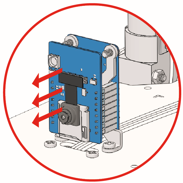
The ESP32-CAM and the Arduino board share the same RX (receive) and TX (transmit) pins. So, when you’re uploading code, you’ll need to first disconnect the ESP32-CAM to avoid any conflicts or potential issues.
Open the
9_hc165_and_ir_obstacle.inofile under the path ofzeus-car-main\examples\9_hc165_and_ir_obstacle.After the code is uploaded successfully, slide the power switch to ON to start the Zeus Car.
Note
Do not unplug the USB in this step, because you need to check the data of the two obstacle avoidance modules on your computer.
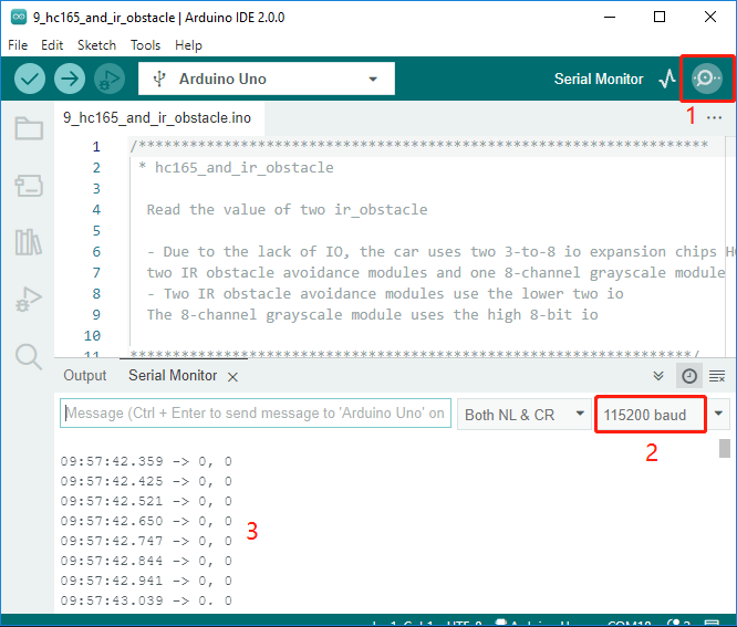
Open the serial monitor and make sure the current baud rate is set to 115200, then you can view the printed data.
If both obstacle avoidance modules do not detect an obstacle, the serial monitor will print
0, 0.Put your hand in front of one of the obstacle avoidance modules, it will print
1, 0or0, 1.
Calibrate the IR obstacle avoidance module.
Start by adjusting the right obstacle avoidance module. During transportation, collisions may cause the transmitter and receiver on the infrared module to tilt. Therefore, you need to manually straighten them.
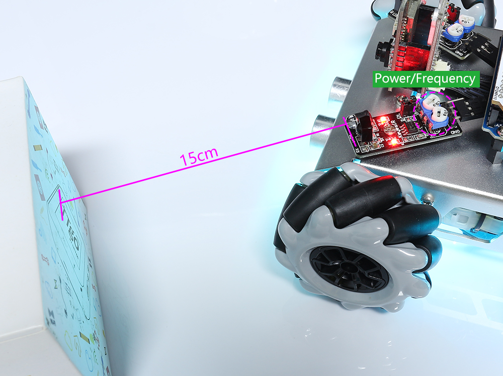
Place an obstacle about 15cm away from the IR obstacle avoidance module.
On the module are two potentiometers, one to adjust the sending power and one to adjust the sending frequency. By adjusting these two potentiometers, you can adjust the detection distance.
Then you can adjust a potentiometer, and if at 15cm, the signal light on the module illuminates, the adjustment is successful; if it doesn’t, adjust another potentiometer.
Calibrate the other obstacle avoidance module in the same way.