Lesson 28 Rotary Encoder
Introduction
A rotary encoder is an electro-mechanical device that converts the angular position or motion of a shaft or axle to an analog or digital code. Rotary encoders are usually placed at the side which is perpendicular to the shaft. Rotary encoders act as sensors for detecting angle, speed, length, position and acceleration in automation field.
Components
1 * SunFounder Uno board
1 * USB data cable
1 * Rotary Encoder module
1 * 5-Pin anti-reverse cable
Principle
There are mainly two types of rotary encoder: absolute and incremental (relative) ones. The output of absolute encoders indicates the current position of the shaft, making them angle transducers. The output of incremental encoders provides information about the motion of the shaft, which is typically further processed elsewhere into information such as speed, distance, and position.
In this experiment, we will use the latter. An incremental encoder is a rotary sensor to turn rotational displacement into a series of digital pulse signals which are then used to control the angular displacement. It generates two-phase square waves whose phase difference is 90°. Usually the two-phase square waves are called channel A and channel B as shown below.
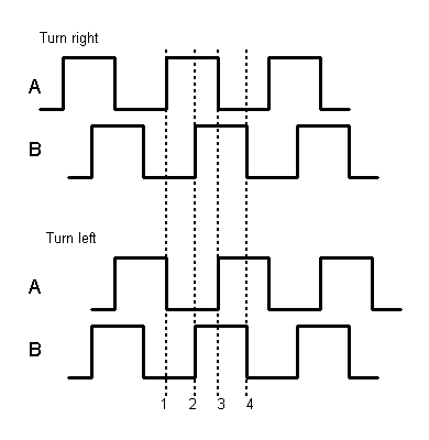
It is difficult to distinguish between the left turn and right turn during SCM programming. However, when using an oscilloscope to observe the left turn and right turn of a switch, you will find a phase difference between the signals of the two output pins as shown below.
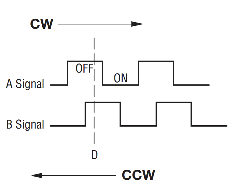
It shows that if output 1 is high and output 2 is high, then the switch rotates clockwise; if output 1 is high and output 2 is low, then the switch rotates counterclockwise. As a result, during SCM programming, if output 1 is high, then you can tell whether the rotary encoder rotates left or right as long as you know the state of output 2.
Experimental Procedures
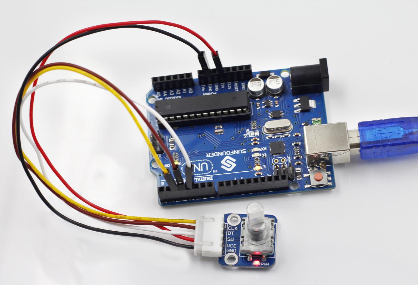
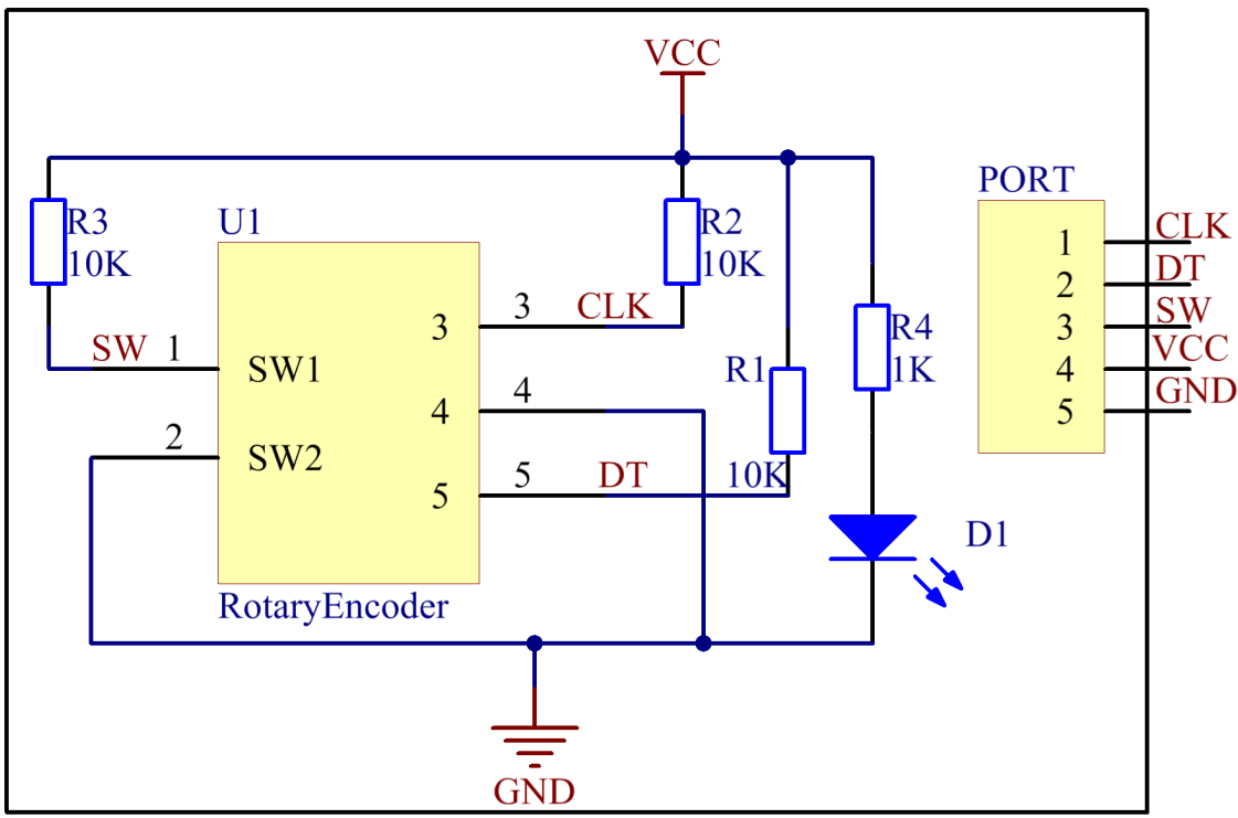
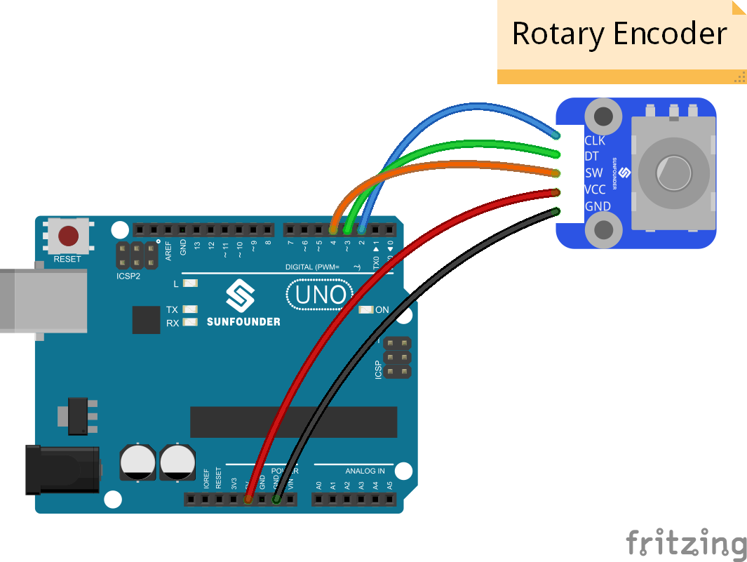
Step 1: Build the circuit
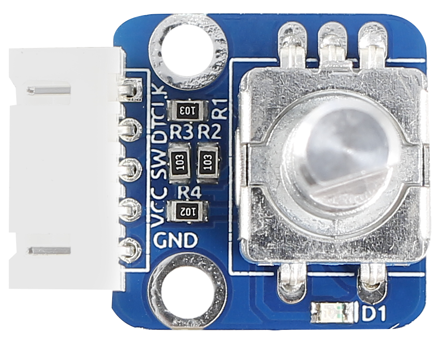
The wiring between the rotary encoder and SunFounder Uno board:
Rotary Encoder |
SunFounder Uno |
CLK |
2 |
DT |
3 |
SW |
4 |
VCC |
5V |
GND |
GND |
Step 2: Open the code file
Step 3: Select correct Board and Port
Step 4: Upload the sketch to the SunFounder Uno board
Code
Now, you can see the angular displacement of the rotary encoder printed on Serial Monitor. When the rotary encoder rotates clockwise, the angular displacement increases; when it does counterclockwise, the value decreases. Press the switch on the rotary encoder, the value will return to zero.