Lesson 17 Photoswitch
Introduction
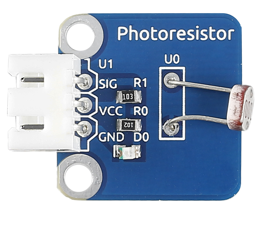
The sensor is in fact a photoresistor which changes its resistance with varying light intensity. It can be used to make a photoswitch.
Components
1 * SunFounder Uno board
1 * USB data cable
1 * Relay module
1 * Photoresistor sensor module
2 * 3-Pin anti-reverse cable
1 * Dupont wire (F to F)
Principle
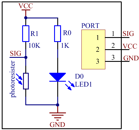
A photoresistor or light-dependent resistor (LDR) or photocell is a light-controlled variable resistor. The resistance of a photoresistor decreases with increasing incident light intensity; in other words, it exhibits photoconductivity. A photoresistor can be applied in light-sensitive detector circuits, and light- and dark-activated switching circuits. In this experiment, hook up the photoresistor to A0 of the SunFounder board, and relay to pin 8. When the value reaches or even exceeds 400, the normally open contact of the relay is closed and the LED at pin 13 on the SunFounder Uno board will light up; otherwise, it will be off. In this way you can make a photoswitch.
Experimental Procedures
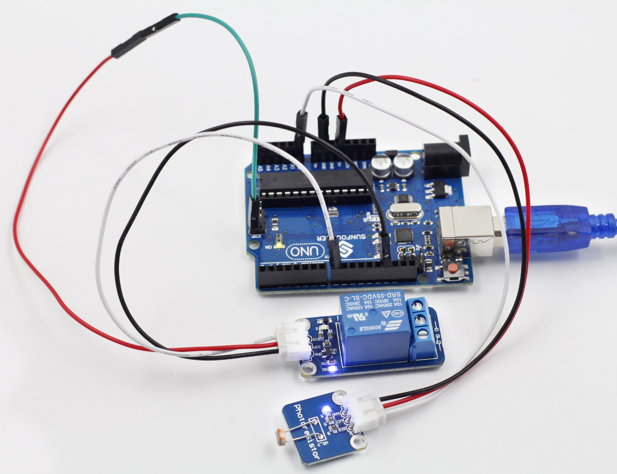
Step 1: Build the circuit
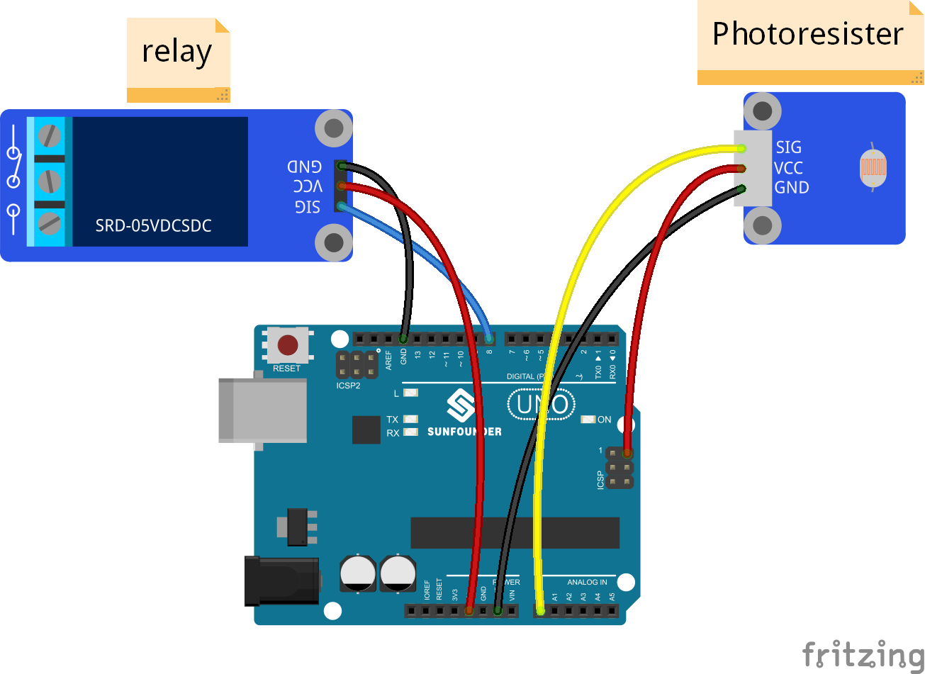
The wiring between the relay and SunFounder Uno board:
Relay |
SunFounder Uno |
GND |
GND |
VCC |
5V |
SIG |
8 |
The wiring between the photoresistor and SunFounder Uno board:
Photoresistor |
SunFounder Uno |
SIG |
A0 |
VCC |
5V |
SIG |
A0 |
Step 2: Open the code file
Step 3: Select correct Board and Port
Step 4: Upload the sketch to the SunFounder Uno board
Code
Now hold the photoresistor with your fingers and check the value at A0 on Serial Monitor. You can see when the resistance is up to 400ohm, the normally open contact of the relay is closed and the LED connected to pin 13 on the SunFounder Uno board lights up; or else, it keeps out.
Summary
In this experiment we’ve use the sensor making a photoswitch. You may try other applications. For instance, connect a bulb to the relay module based on the circuit. Then when it gets dimmer, the normally open contact of the relay is closed and the bulb will light up. The same way applies to the street light.