Lesson 31 IR Obstacle Avoidance Sensor
Introduction
An IR Obstacle Sensor works in accordance with the infrared reflection principle to detect obstacles. When there is no object, the infrared receiver receives no signals; when there is an object ahead which blocks and reflects the infrared light, the infrared receiver will receive signals.
Components
1 * SunFounder Uno board
1 * USB data cable
1 * Obstacle avoidance sensor module
1 * 3-Pin anti-reverse cable
Principle
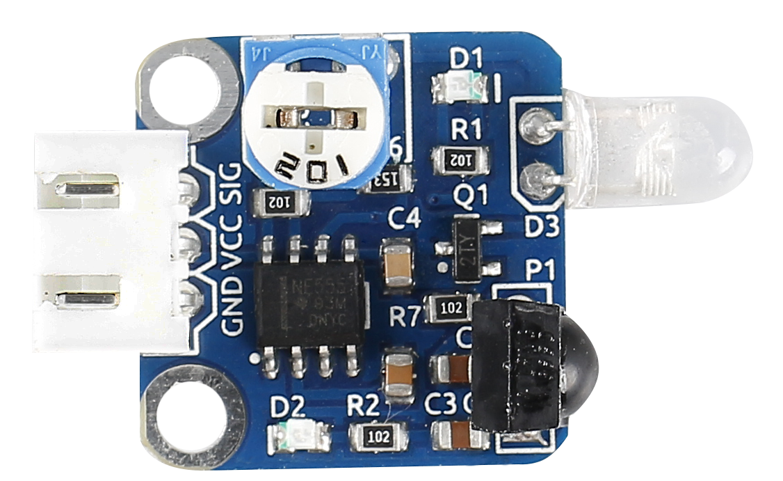
An obstacle avoidance sensor mainly consists of an infrared transmitter, an infrared receiver and a potentiometer. According to the reflecting character of an object, if there is no obstacle, the emitted infrared ray will weaken with the distance it spreads and finally disappear. If there is an obstacle, when the infrared ray encounters it, the ray will be reflected back to the infrared receiver. Then the infrared receiver detects this signal and confirms an obstacle in front.
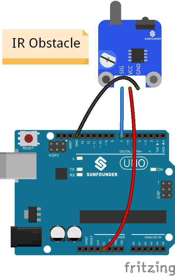
In this experiment, we will use an Obstacle Avoidance Sensor module and the LED attached to pin 13 of the SunFounder Uno board to build a simple circuit.
Since the LED has been attached to pin 13, connect the pin SIG to digital pin 7 of the Uno board. When the Obstacle Avoidance Sensor detects an obstacle, the LED will be on. Otherwise it will be off.
Note
The detection distance of the infrared sensor is adjustable - you may adjust it by the potentiometer.
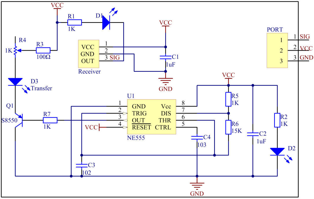
The schematic diagram is as follows:
Experimental Procedures
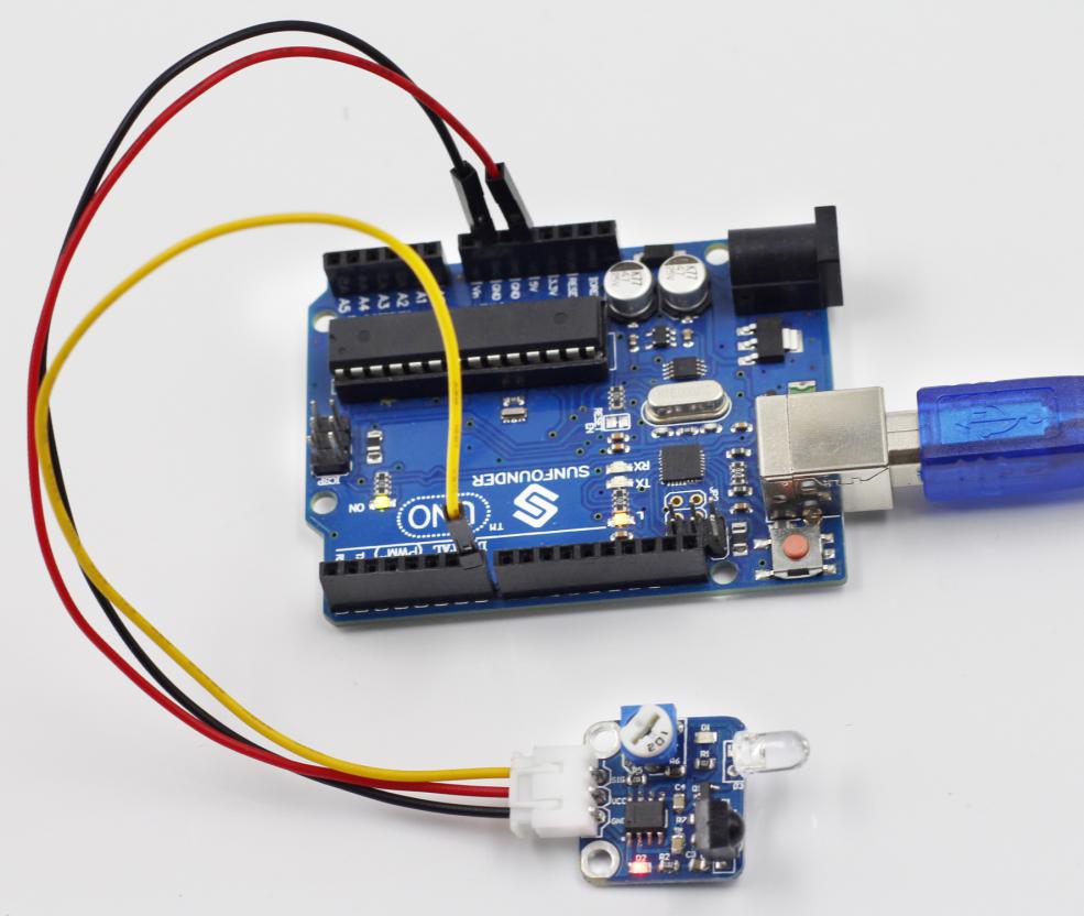
Step 1: Build the circuit
Step 2: Open the code file
Step 3: Select correct Board and Port
Step 4: Upload the sketch to the SunFounder Uno board
Code
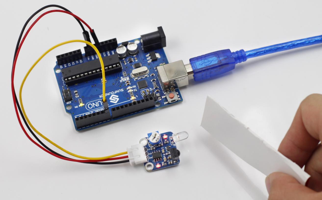
Now, place a piece of paper in front of the Obstacle Avoidance Sensor, and the LED attached to pin 13 on the SunFounder Uno board will light up.
Note
The obstacle should better be white.
Before
With obstacle