Lesson 20 Blinking an LED by Potentiometer
Introduction
A potentiometer can help to control the interval at which the LED on the SunFounder board blinks.
Components
1 * SunFounder Uno board
1 * 3-Pin anti-reverse cable
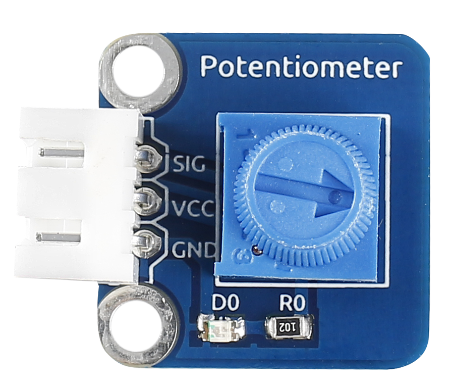
1 * Potentiometer module
1 * USB cable
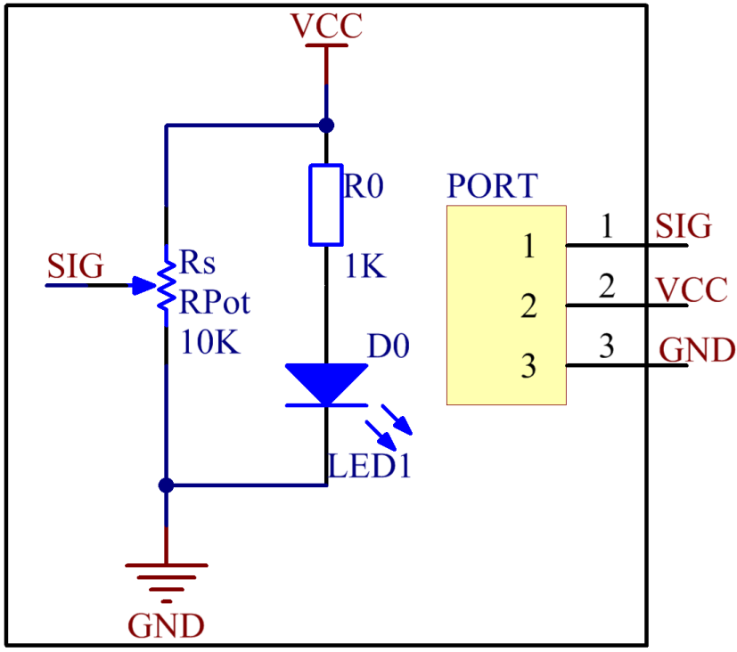
Principle
An analog potentiometer is an analog electronic component. What’s the difference between an analog one and a digital one? Simply put, a digital potentiometer refers to just two states like on/off, high/low levels, i.e. either 0 or 1, while a digital one supports analog signals like a number from 1 to 1000. The signal value changes over time instead of keeping an exact number. Analog signals include light intensity, humidity, temperature, and so on.
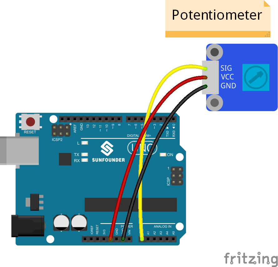
In this experiment, hook up the pin SIG of the potentiometer module to A0 of the SunFounder Uno board and check the value at A0. Then use the value to control the interval at which the LED connected with pin 13 of the Uno board blinks. Rotate the shaft of the potentiometer and the LED blink interval will increases or decreases.
Experimental Procedures
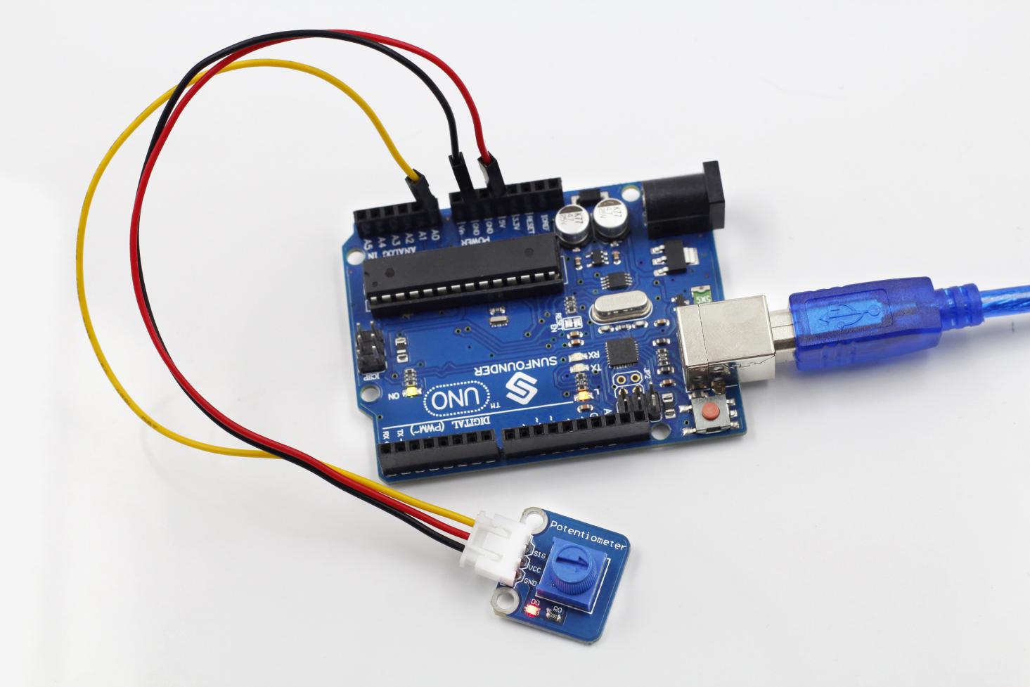
Step 1: Build the circuit
Step 2: Open the code file
Step 3: Select correct Board and Port
Step 4: Upload the sketch to the SunFounder Uno board
Code
Rotate the shaft of the potentiometer and the interval at which the LED attached to pin 13 of the SunFounder Uno blinks will increase or decrease.