Lesson 3 Switch Hall Sensor
Introduction
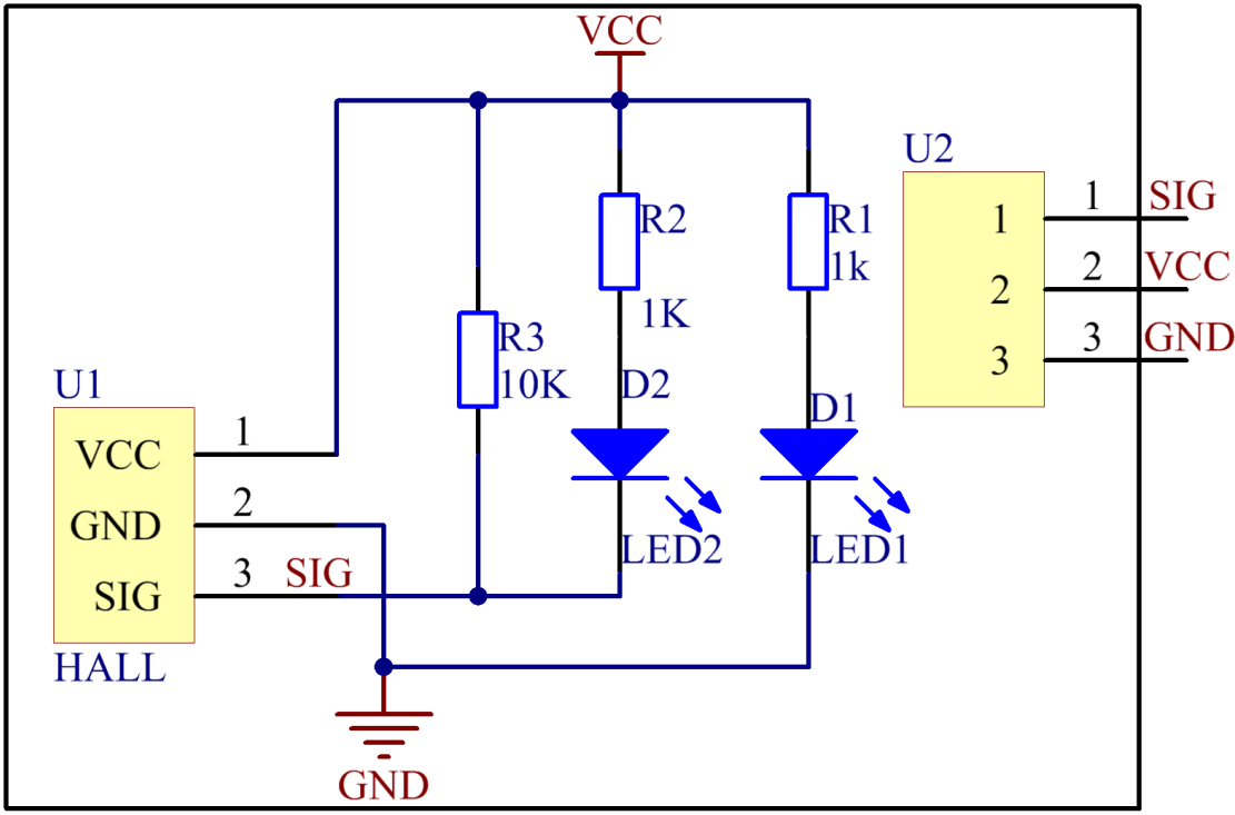
A switch Hall sensor consists of voltage regulator, Hall element, differential amplifier, Schmitt trigger, and output terminal. It outputs digital values.
Components
1 * SunFounder Uno board
1 * USB data cable
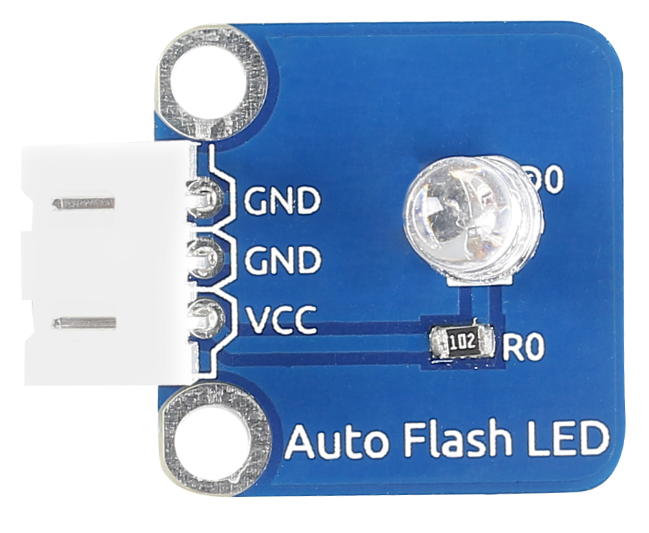
1 * Switch Hall sensor module
2 * 3-Pin anti-reverse cable
1 * Passive buzzer
1 * Magnet
Principle
Hook up the switch Hall sensor module with pin 8 of the SunFounder Uno, and the buzzer to pin 7. When an energized conductor approaches the module, the output terminal SIG outputs low level; the buzzer beeps and at the same time the corresponding LED lights up.
Experimental Procedures
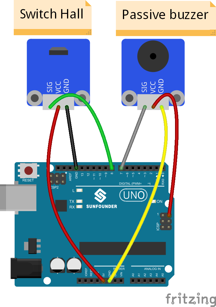
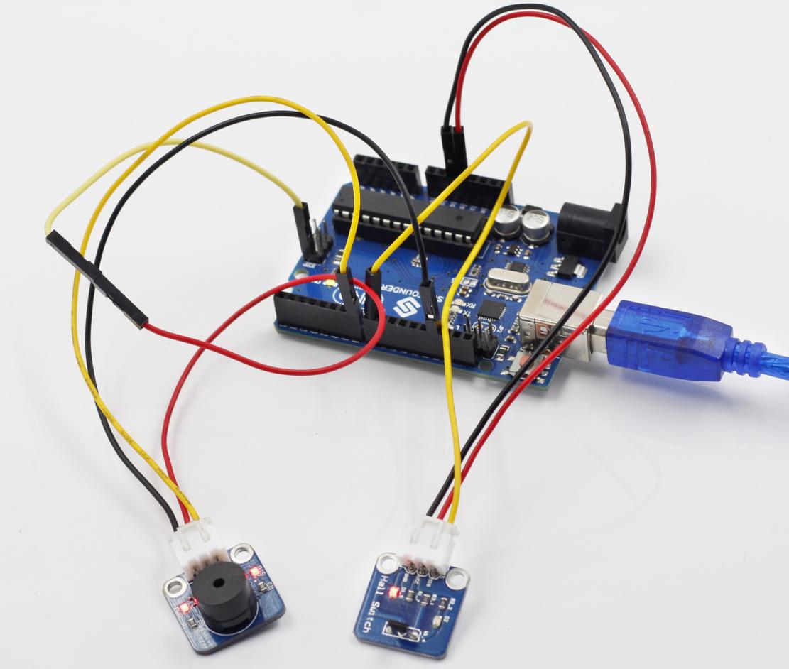
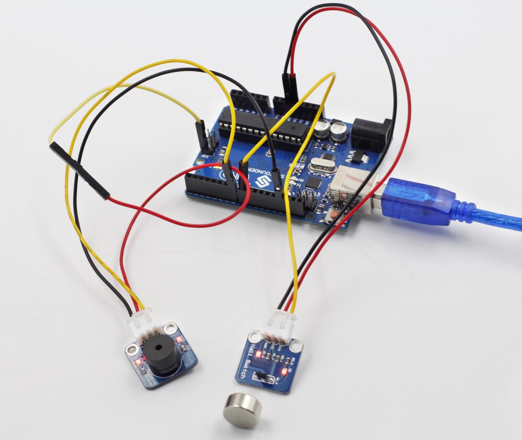
Step 1: Build the circuit
The wiring between the switch Hall sensor and SunFounder Uno board:
Switch Hall Sensor |
SunFounder Uno |
SIG |
8 |
VCC |
5V |
GND |
GND |
The wiring between the passive buzzer and SunFounder Uno board:
Passive Buzzer |
SunFounder Uno |
SIG |
7 |
VCC |
5V |
GND |
GND |
Step 2: Open the code file
Step 3: Select correct Board and Port
Step 4: Upload the sketch to the SunFounder Uno board
Code
Now, if a magnet approaches the switch Hall sensor, the indicator light on the sensor will light up and the buzzer will beep. At the same time, the LED attached to pin 13 on the SunFounder Uno board will also light up.
Before
After