Lesson 32 Color Detection
Introduction

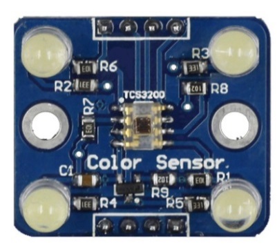
The Color Sensor is a complete color detector. It consists of a TAOS TCS3200 RGB sensor chip and 4 white LEDs. It can detect and measure a nearly limitless range of visible colors to a certain degree.
Components
1 * SunFounder Uno board
1 * USB data cable
1 * Color sensor
1 * 4-Pin anti-reverse cable
1 * 3-Pin anti-reverse cable
Principle
The color of an object we can see in fact is the chromatic light the object reflects in the white light (sunlight) after it absorbs the rest ones. The white color is a mixture of various visible colors, which means it includes each colored light like red (R), yellow (Y), green (G), blue (B), and purple (P). Based on the theory of three primary colors, any color is made by mixing the three primary colors (red, green, and blue) in a certain proportion.
Thus, knowing the proportion you can get the color of the tested object. For TCS3200, when a color filter is selected, it only allows a specific primary color to pass through and blocks the other two colors. With the light intensity value of the three primary colors, by analysis we can know the color of light reflected to TCS3200D.
The TCS3200D sensor has 4 types of filter: red filter, green filter, blue filter, and clear with no filter. The filter is selected based on the high/low of pin S2 and S3 on the module (see the table below):
S2 |
S3 |
Photo Diode Type |
L |
L |
Red |
L |
H |
Blue |
H |
L |
Clear (no filter) |
H |
H |
Green |
The module contains a programmable converter which transforms colorlight to frequency. When the part of RGB colors in the light reflected by the object passes through the filter selected to the TAOS TCS3200RGB chip, the built-in oscillator outputs square waves. The frequency of the waves is directly proportional to the light intensity – the more intense the light is, the higher is the frequency. Also, the frequency of the OUT pin on the sensor module is proportional to that of the oscillator; the proportion depends on the high/low of pin S0 and S1, as shown in the table.
S0 |
S1 |
OUTPUT Frequency Scaling (f0) |
L |
L |
Power Down |
L |
H |
2% |
H |
L |
20% |
H |
H |
100% |
The schematic diagram of the module:

Experimental Procedures
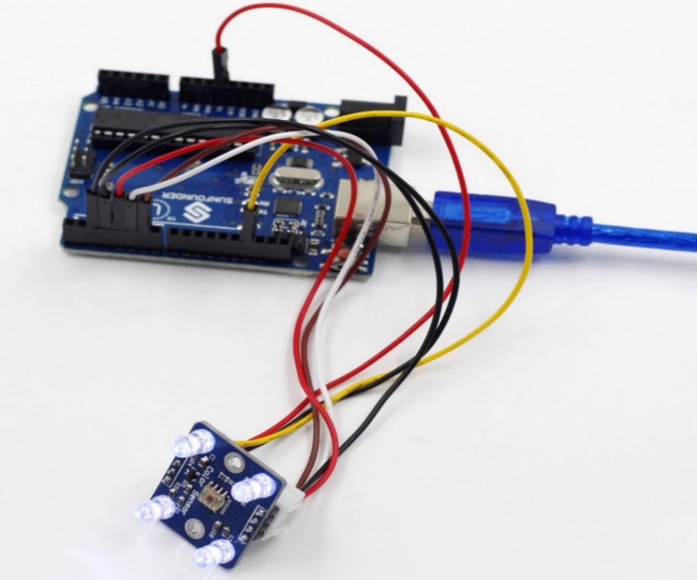
Step 1: Build the circuit
The wiring between the color sensor and SunFounder Uno board:
Color Sensor |
SunFounder Uno |
GND |
GND |
VCC |
5V |
OUT |
2 |
S0 |
3 |
S1 |
4 |
S2 |
5 |
S3 |
6 |

Step 2: Open the code file
Step 3: Select correct Board and Port
Step 4: Upload the sketch to the SunFounder Uno board
Code
Now you may check the RGB value of the color on Serial Monitor.
