Lesson 24 Rainbow LED
Introduction
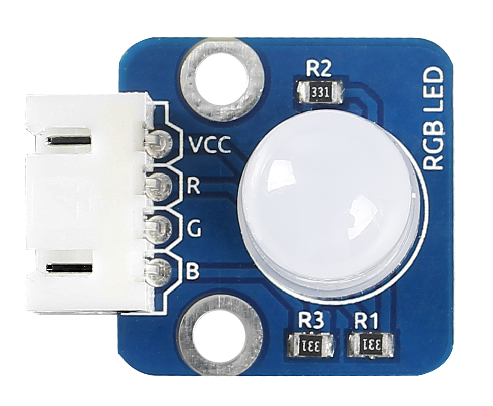
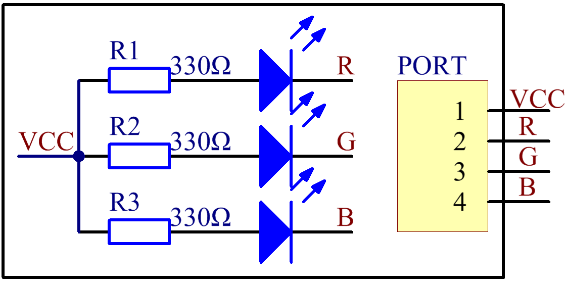
RGB LED modules can emit various colors of light. Three LEDs of red, green, and blue are packaged into a transparent or semitransparent plastic shell with four pins led out. The three primary colors, red, green, and blue, can be mixed and compose all kinds of colors by brightness, so you can make an RGB LED emit colorful light by controlling the circuit.
Components
1 * SunFounder Uno board
1 * USB data cable
1 * RGB LED module
1 * 4-Pin anti-reverse cable
Principle
In this experiment, we will use PWM technology to the brightness of RGB.
Pulse Width Modulation, or PWM, is a technique for getting analog results with digital means. Digital control is used to create a square wave, a signal switched between on and off. This on-off pattern can simulate voltages in between full on (5V) and off (0V) by changing the portion of the time the signal spends on versus the time that the signal spends off. The duration of “on time” is called the pulse width. To get varying analog values, you change, or modulate, that pulse width. If you repeat this on-off pattern fast enough with an LED for example, the result is as if the signal is a steady voltage between 0 and 5v controlling the brightness of the LED. (See the PWM description on the official website of Arduino).
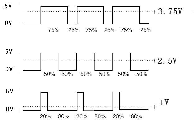
We can see from the oscillogram above that the amplitude of DC voltage output is 5V. However, the actual voltage output is only 3.75V through PWM, for the high level only takes up 75% of the total voltage within a period.
Here are the three basic parameters of PWM:
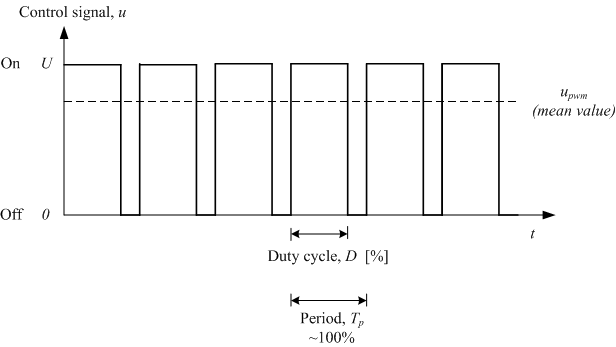
The term duty cycle describes the proportion of “on” time to the regular interval or “period” of time
Period describes the reciprocal of pulses in one second.
The voltage amplitude is 0-5V.
Here we input any value between 0 and 255 to the three pins of the RGB LED to make it display different colors.
RGB LEDs can be categorized into common anode LED and common cathode LED. In this experiment, we use a common anode RGB LED.
Experimental Procedures
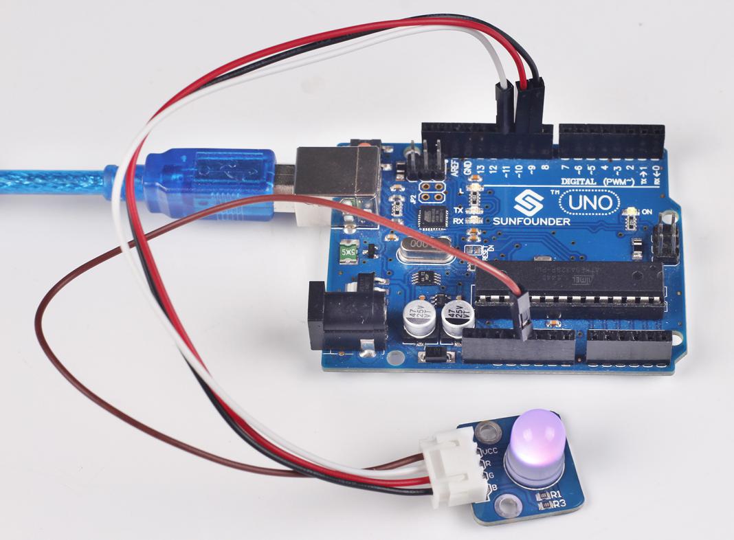
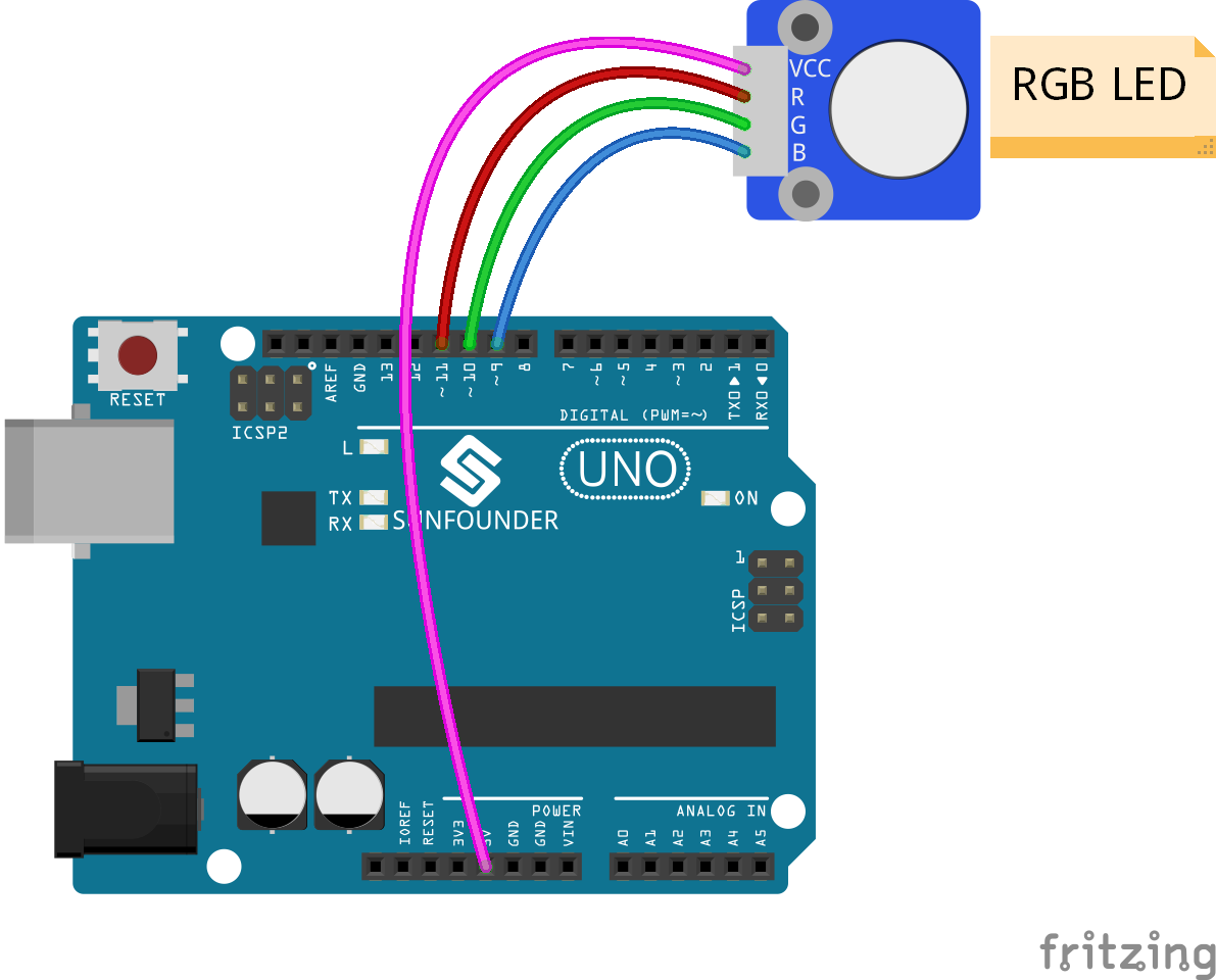
Step 1: Build the circuit
Step 2: Open the code file
Step 3: Select correct Board and Port
Step 4: Upload the sketch to the SunFounder Uno board
Code
Now, you can see RGB LED flash red, green and blue first, and then change to red, orange, yellow, green, blue, indigo and purple.