Nota
¡Hola! Bienvenido a la comunidad de entusiastas de SunFounder Raspberry Pi & Arduino & ESP32 en Facebook. Profundiza en Raspberry Pi, Arduino y ESP32 junto con otros entusiastas.
¿Por qué unirse?
Soporte experto: Resuelve problemas postventa y desafíos técnicos con la ayuda de nuestra comunidad y equipo.
Aprende y comparte: Intercambia consejos y tutoriales para mejorar tus habilidades.
Vistas previas exclusivas: Obtén acceso anticipado a nuevos anuncios de productos y adelantos.
Descuentos especiales: Disfruta de descuentos exclusivos en nuestros productos más recientes.
Promociones y sorteos festivos: Participa en sorteos y promociones de temporada.
👉 ¿Listo para explorar y crear con nosotros? Haz clic en [Aquí] y únete hoy mismo.
3.1.8 Monitor de sobrecalentamiento (MCP3008)
Nota
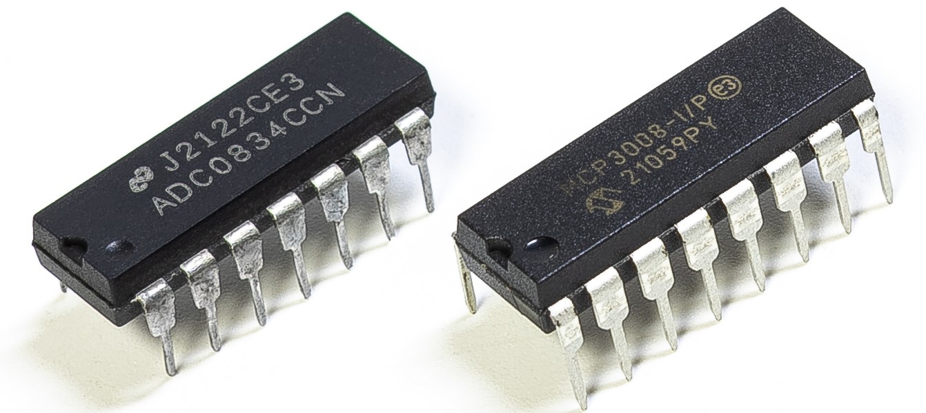
Dependiendo de la versión de tu kit, identifica si tienes ADC0834 o MCP3008 y continúa con la sección correspondiente.
Introducción
Puede que desees crear un dispositivo de monitoreo de sobrecalentamiento aplicable a diversas situaciones. Por ejemplo, en una fábrica, si queremos tener una alarma y apagado automático cuando un circuito se sobrecalienta. En este proyecto utilizaremos un termistor, un joystick, un zumbador, un LED y una pantalla LCD para fabricar un dispositivo inteligente de monitoreo de temperatura cuyo umbral es ajustable.
Componentes necesarios
En este proyecto, necesitamos los siguientes componentes.
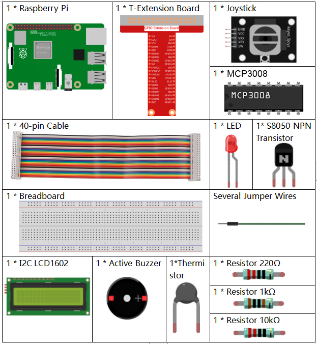
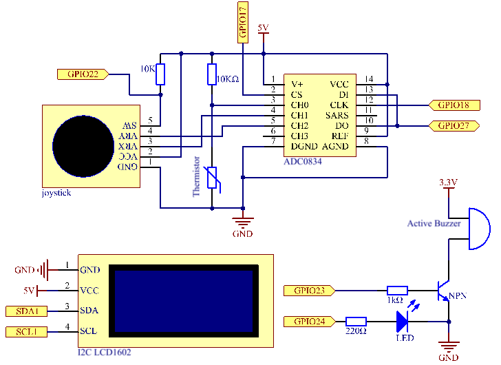
Diagrama esquemático
T-Board Name |
físico |
wiringPi |
BCM |
SPICE0 |
Pin 24 |
10 |
8 |
SPIMOSI |
Pin 19 |
12 |
10 |
SPIMISO |
Pin 21 |
13 |
9 |
SPISCLK |
Pin 23 |
14 |
11 |
GPIO22 |
Pin15 |
3 |
22 |
GPIO23 |
Pin16 |
4 |
23 |
GPIO24 |
Pin18 |
5 |
24 |
SDA1 |
Pin 3 |
||
SCL1 |
Pin 5 |
Procedimiento experimental
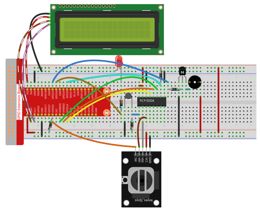
Paso 1: Monta el circuito.
Para usuarios de lenguaje C
Paso 2: Ve a la carpeta del código.
cd ~/davinci-kit-for-raspberry-pi/c/3.1.8-2/
Paso 3: Compila el código.
gcc 3.1.8_OverheatMonitor.c -lm -lwiringPi
Paso 4: Ejecuta el archivo compilado.
sudo ./a.out
Cuando se ejecute el código, la temperatura actual y el umbral de alta temperatura 40 se mostrarán en la I2C LCD1602. Si la temperatura actual es mayor que el umbral, el zumbador y el LED se activarán para alertarte.
El joystick sirve para ajustar el umbral de alta temperatura. Moviendo el joystick en el eje X o Y podrás aumentar o disminuir el umbral. Pulsando el joystick nuevamente lo restablecerás a su valor inicial.
Nota
Si aparece el error
wiringPi.h: No such file or directory, consulta Instalar y Comprobar WiringPi.Si aparece el error
Unable to open I2C device: No such file or directory, consulta Configuración de I²C para habilitar I2C y verificar el cableado.Si el código y el cableado están correctos pero la LCD no muestra nada, ajusta el potenciómetro en la parte trasera para aumentar el contraste.
Explicación del código
int read_ADC(int channel) {
    if (channel < 0 || channel > 7) return -1;
    unsigned char buffer[3];
    buffer[0] = 1;
    buffer[1] = (8 + channel) << 4;
    buffer[2] = 0;
    wiringPiSPIDataRW(SPI_CHANNEL, buffer, 3);
    return ((buffer[1] & 0x03) << 8) | buffer[2];
}
Lee un valor analógico de 10 bits desde el canal MCP3008 (CH0–CH7) usando SPI y devuelve un entero de 0 a 1023.
int get_joystick_value() {
    int x = read_ADC(1);
    int y = read_ADC(2);

    if (x > 900)      return 1;   // Derecha
    else if (x < 100) return -1;  // Izquierda
    else if (y > 900) return -10; // Arriba
    else if (y < 100) return 10;  // Abajo
    else              return 0;
}
Lee los valores analógicos X e Y del joystick desde CH1 y CH2. Devuelve un número indicando la dirección según los umbrales.
void upper_tem_setting() {
    write_lcd(0,0, "Upper Adjust:");

    int change = get_joystick_value();

    if (change != 0 && change != lastJoystickChange) {
        upperTem += change;
        lastJoystickChange = change;
    }
    else if (change == 0) {
        lastJoystickChange = 0;
    }

    char str[6];
    snprintf(str, sizeof(str), "%d", upperTem);
    write_lcd(0,1, str);
    write_lcd(strlen(str),1, "            ");

    delay(100);
}
Permite ajustar el umbral de temperatura usando el joystick. Evita cambios repetidos cuando se mantiene la dirección.
double temperature() {
    int raw = read_ADC(0);
    double Vr = 3.3 * ((double)raw / 1023.0);
    double Rt = 10000.0 * Vr / (3.3 - Vr);
    double tempK = 1.0 / ((log(Rt/10000.0)/3950.0) + 1.0/(273.15+25.0));
    return tempK - 273.15;
}
Lee el valor analógico desde CH0 conectado al termistor y usa la ecuación de Steinhart–Hart para calcular la temperatura en grados Celsius.
void monitoring_temp() {
    char str[6];
    double cel = temperature();
    snprintf(str, sizeof(str), "%.2f", cel);
    write_lcd(0,0, "Temp: ");
    write_lcd(6,0, str);

    snprintf(str, sizeof(str), "%d", upperTem);
    write_lcd(0,1, "Upper: ");
    write_lcd(7,1, str);
    delay(100);

    if (cel >= upperTem) {
        digitalWrite(buzzPin, HIGH);
        digitalWrite(LedPin,  HIGH);
    } else {
        digitalWrite(buzzPin, LOW);
        digitalWrite(LedPin,  LOW);
    }
}
Lee continuamente la temperatura y la muestra junto con el umbral. Si la temperatura supera el umbral, activa el zumbador y el LED.
void setup_all() {
    fd = wiringPiI2CSetup(LCDAddr);
    lcd_init();
    if (wiringPiSetup() == -1 || wiringPiSPISetup(SPI_CHANNEL, SPI_SPEED) == -1) {
        printf("Setup failed!\n");
        return;
    }
    pinMode(Joy_BtnPin, INPUT);
    pullUpDnControl(Joy_BtnPin, PUD_UP);
    pinMode(buzzPin, OUTPUT);
    pinMode(LedPin,  OUTPUT);
}
Inicializa la LCD, SPI y los pines GPIO para el botón del joystick, el zumbador y el LED. Activa la resistencia pull-up para el botón del joystick.
int main(void) {
    setup_all();

    int lastBtnState = HIGH;
    int stage = 0;

    while (1) {
        int curBtn = digitalRead(Joy_BtnPin);
        if (curBtn == HIGH && lastBtnState == LOW) {
            stage = (stage + 1) % 2;
            lastJoystickChange = 0;
            delay(100);
            lcd_clear();
        }
        lastBtnState = curBtn;

        if (stage == 1)
            upper_tem_setting();
        else
            monitoring_temp();
    }

    return 0;
}
El bucle principal alterna entre dos modos:
Monitoreo de temperatura.
Ajuste del límite máximo usando el joystick.
El cambio de modo ocurre cuando se suelta el botón del joystick (detecto de flanco ascendente).
Para usuarios del lenguaje Python
Paso 2: Configura la interfaz SPI e instala la biblioteca spidev (consulta :ref:spi_configuration para obtener instrucciones detalladas). Si ya has completado estos pasos, puedes omitir este.
Paso 3: Ve a la carpeta del código.
cd ~/davinci-kit-for-raspberry-pi/python
Paso 4: Ejecuta el archivo ejecutable.
sudo python3 3.1.8-2_OverheatMonitor.py
Mientras el código se ejecuta, la temperatura actual y el umbral de alta temperatura 40 se muestran en I2C LCD1602. Si la temperatura actual es mayor que el umbral, el zumbador y el LED comenzarán a alertarte.
El Joystick sirve para que, al presionarlo, puedas ajustar el umbral de alta temperatura. Moviendo el Joystick en la dirección del eje X o Y se puede ajustar (subir o bajar) el umbral actual de alta temperatura. Presiona el Joystick nuevamente para restablecer el umbral a su valor inicial.
Nota
Si aparece el error
FileNotFoundError: [Errno 2] No such file or directory: '/dev/i2c-1', debes consultar Configuración de I²C para habilitar el I2C.Si aparece el error
ModuleNotFoundError: No module named 'smbus2', ejecutasudo pip3 install smbus2.Si aparece el error
OSError: [Errno 121] Remote I/O error, significa que el módulo está mal cableado o dañado.Si el código y el cableado están bien, pero la LCD aún no muestra contenido, gira el potenciómetro en la parte trasera para aumentar el contraste.
Advertencia
Si aparece el error RuntimeError: Cannot determine SOC peripheral base address, consulta Si gpiozero no funciona.
Código
Nota
Puedes Modificar/Restablecer/Copiar/Ejecutar/Detener el código a continuación. Pero antes de eso, debes ir a la ruta del código fuente como davinci-kit-for-raspberry-pi/python. Después de modificar el código, puedes ejecutarlo directamente para ver el efecto.
#!/usr/bin/env python3

import RPi.GPIO as GPIO
import spidev
import time
import math
import LCD1602

# Definición de pines GPIO
JOY_BTN_PIN = 22  # Pin del botón
BUZZER_PIN = 23   # Pin del zumbador
LED_PIN = 24      # Pin del LED

# Inicializar GPIO
GPIO.setmode(GPIO.BCM)
GPIO.setup(JOY_BTN_PIN, GPIO.IN, pull_up_down=GPIO.PUD_UP)
GPIO.setup(BUZZER_PIN, GPIO.OUT)
GPIO.setup(LED_PIN, GPIO.OUT)

# Umbral inicial de temperatura alta
upperTem = 40

# Inicializar SPI para MCP3008
spi = spidev.SpiDev()
spi.open(0, 0)
spi.max_speed_hz = 1000000  # 1 MHz

# Inicializar LCD1602
LCD1602.init(0x27, 1)

def read_adc(channel):
   """
   Lee el valor analógico del MCP3008 (0–7)
   """
   if channel < 0 or channel > 7:
      return -1
   adc = spi.xfer2([1, (8 + channel) << 4, 0])
   value = ((adc[1] & 0x03) << 8) | adc[2]
   return value

def get_joystick_value():
   """
   Lee los valores del joystick y devuelve un cambio basado en su posición.
   """
   x_val = read_adc(1)
   y_val = read_adc(2)
   if x_val > 800:
      return 1
   elif x_val < 200:
      return -1
   elif y_val > 800:
      return -10
   elif y_val < 200:
      return 10
   else:
      return 0

def upper_tem_setting():
   """
   Ajusta y muestra el umbral de temperatura alta en la LCD.
   """
   global upperTem
   LCD1602.write(0, 0, 'Upper Adjust: ')
   change = int(get_joystick_value())
   upperTem += change
   strUpperTem = str(upperTem)
   LCD1602.write(0, 1, strUpperTem)
   LCD1602.write(len(strUpperTem), 1, '              ')
   time.sleep(0.1)

def temperature():
   """
   Lee la temperatura actual del sensor y la devuelve en grados Celsius.
   """
   analogVal = read_adc(0)
   Vr = 3.3 * analogVal / 1023.0
   if Vr == 0:
      return 0
   Rt = 10000.0 * (3.3 - Vr) / Vr
   tempK = 1.0 / (((math.log(Rt / 10000.0)) / 3950.0) + (1.0 / (273.15 + 25.0)))
   Cel = tempK - 273.15
   return round(Cel, 2)

def monitoring_temp():
   """
   Supervisa y muestra la temperatura actual y el umbral de temperatura alta.
   Activa el zumbador y el LED si la temperatura supera el límite.
   """
   global upperTem
   Cel = temperature()
   LCD1602.write(0, 0, 'Temp: ')
   LCD1602.write(0, 1, 'Upper: ')
   LCD1602.write(6, 0, str(Cel))
   LCD1602.write(7, 1, str(upperTem))
   time.sleep(0.1)
   if Cel >= upperTem:
      GPIO.output(BUZZER_PIN, GPIO.HIGH)
      GPIO.output(LED_PIN, GPIO.HIGH)
   else:
      GPIO.output(BUZZER_PIN, GPIO.LOW)
      GPIO.output(LED_PIN, GPIO.LOW)

# Bucle principal
try:
   lastState = GPIO.input(JOY_BTN_PIN)
   stage = 0
   while True:
      currentState = GPIO.input(JOY_BTN_PIN)
      if currentState == GPIO.HIGH and lastState == GPIO.LOW:
            stage = (stage + 1) % 2
            time.sleep(0.1)
            LCD1602.clear()
      lastState = currentState

      if stage == 1:
            upper_tem_setting()
      else:
            monitoring_temp()

except KeyboardInterrupt:
   pass

finally:
   LCD1602.clear()
   GPIO.cleanup()
   spi.close()
Explicación del código
Importar bibliotecas
Esta sección carga las bibliotecas necesarias para GPIO, SPI, pantalla LCD, retardos y operaciones matemáticas.
#!/usr/bin/env python3
import RPi.GPIO as GPIO
import spidev
import time
import math
import LCD1602
Configuración de GPIO y dispositivos
Define los números de pines GPIO para el botón del joystick, el zumbador y el LED, y configura los modos GPIO.
JOY_BTN_PIN = 22  # Pin del botón
BUZZER_PIN = 23   # Pin del zumbador
LED_PIN = 24      # Pin del LED

GPIO.setmode(GPIO.BCM)
GPIO.setup(JOY_BTN_PIN, GPIO.IN, pull_up_down=GPIO.PUD_UP)
GPIO.setup(BUZZER_PIN, GPIO.OUT)
GPIO.setup(LED_PIN, GPIO.OUT)
Inicialización de SPI y LCD
Inicia la interfaz SPI para el MCP3008 e inicializa la pantalla LCD1602 con dirección I2C 0x27.
upperTem = 40
spi = spidev.SpiDev()
spi.open(0, 0)
spi.max_speed_hz = 1000000

LCD1602.init(0x27, 1)
Lectura de valor ADC
Lee datos analógicos desde el MCP3008 vía SPI. El canal debe estar en el rango de 0–7.
def read_adc(channel):
   if channel < 0 or channel > 7:
      return -1
   adc = spi.xfer2([1, (8 + channel) << 4, 0])
   value = ((adc[1] & 0x03) << 8) | adc[2]
   return value
Detección de movimiento del joystick
Verifica los valores de los ejes X/Y del joystick y devuelve cuánto debe cambiar el umbral.
def get_joystick_value():
   x_val = read_adc(1)
   y_val = read_adc(2)
   if x_val > 800:
      return 1
   elif x_val < 200:
      return -1
   elif y_val > 800:
      return -10
   elif y_val < 200:
      return 10
   else:
      return 0
Ajuste del umbral de temperatura alta
Muestra «Upper Adjust» en la LCD y ajusta el umbral usando el joystick.
def upper_tem_setting():
   global upperTem
   LCD1602.write(0, 0, 'Upper Adjust: ')
   change = int(get_joystick_value())
   upperTem += change
   strUpperTem = str(upperTem)
   LCD1602.write(0, 1, strUpperTem)
   LCD1602.write(len(strUpperTem), 1, '              ')
   time.sleep(0.1)
Cálculo de la temperatura
Convierte la lectura del sensor en voltaje, resistencia y finalmente en grados Celsius usando la aproximación de Steinhart–Hart.
def temperature():
   analogVal = read_adc(0)
   Vr = 3.3 * analogVal / 1023.0
   if Vr == 0:
      return 0
   Rt = 10000.0 * (3.3 - Vr) / Vr
   tempK = 1.0 / (((math.log(Rt / 10000.0)) / 3950.0) + (1.0 / (273.15 + 25.0)))
   Cel = tempK - 273.15
   return round(Cel, 2)
Monitoreo de temperatura
Comprueba y muestra continuamente la temperatura y el límite. Activa el zumbador y el LED si la temperatura supera el umbral.
def monitoring_temp():
   global upperTem
   Cel = temperature()
   LCD1602.write(0, 0, 'Temp: ')
   LCD1602.write(0, 1, 'Upper: ')
   LCD1602.write(6, 0, str(Cel))
   LCD1602.write(7, 1, str(upperTem))
   time.sleep(0.1)
   if Cel >= upperTem:
      GPIO.output(BUZZER_PIN, GPIO.HIGH)
      GPIO.output(LED_PIN, GPIO.HIGH)
   else:
      GPIO.output(BUZZER_PIN, GPIO.LOW)
      GPIO.output(LED_PIN, GPIO.LOW)
Lógica principal del programa
Alterna entre el monitoreo de temperatura y el ajuste de umbral cuando se presiona el botón del joystick.
try:
   lastState = GPIO.input(JOY_BTN_PIN)
   stage = 0
   while True:
      currentState = GPIO.input(JOY_BTN_PIN)
      if currentState == GPIO.HIGH and lastState == GPIO.LOW:
            stage = (stage + 1) % 2
            time.sleep(0.1)
            LCD1602.clear()
      lastState = currentState

      if stage == 1:
            upper_tem_setting()
      else:
            monitoring_temp()
Limpieza al salir
Garantiza la liberación adecuada de recursos GPIO y SPI cuando se presiona Ctrl+C.
except KeyboardInterrupt:
   pass
finally:
   LCD1602.clear()
   GPIO.cleanup()
   spi.close()