Note
Hello, welcome to the SunFounder Raspberry Pi & Arduino & ESP32 Enthusiasts Community on Facebook! Dive deeper into Raspberry Pi, Arduino, and ESP32 with fellow enthusiasts.
Why Join?
Expert Support: Solve post-sale issues and technical challenges with help from our community and team.
Learn & Share: Exchange tips and tutorials to enhance your skills.
Exclusive Previews: Get early access to new product announcements and sneak peeks.
Special Discounts: Enjoy exclusive discounts on our newest products.
Festive Promotions and Giveaways: Take part in giveaways and holiday promotions.
👉 Ready to explore and create with us? Click [here] and join today!
2.2.1 Photoresistor(MCP3008)
Note
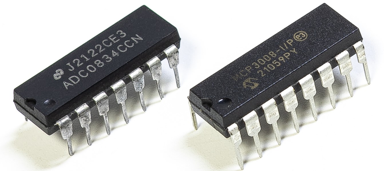
Depending on your kit version, please identify whether you have ADC0834 or MCP3008 and proceed with the matching section.
Introduction
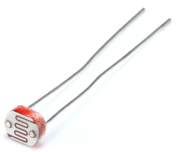
Photoresistor is a commonly used component of ambient light intensity in life. It helps the controller to recognize day and night and realize light control functions such as night lamp. This project is very similar to potentiometer, and you might think it changing the voltage to sensing light.
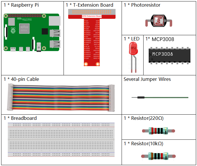
Required Components
In this project, we need the following components.
Principle
A photoresistor or photocell is a light-controlled variable resistor. The resistance of a photoresistor decreases with increasing incident light intensity; in other words, it exhibits photo conductivity. A photoresistor can be applied in light-sensitive detector circuits, and light- and darkness-activated switching circuits.
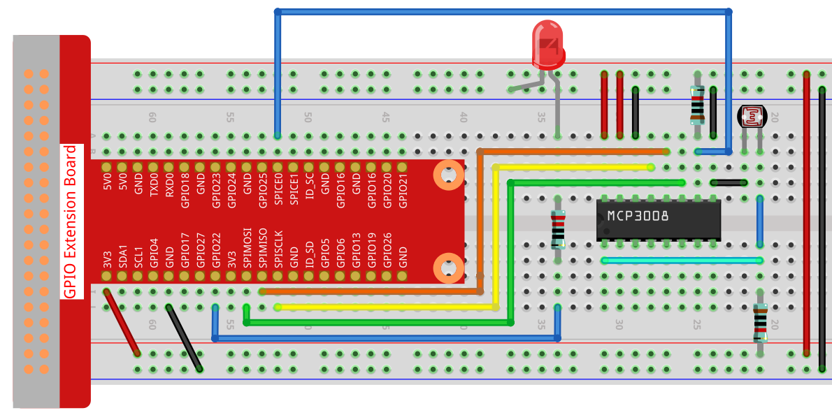
Schematic Diagram
T-Board Name |
physical |
WiringPi |
BCM |
|---|---|---|---|
SPICE0 |
pin24 |
10 |
8 |
SPIMOSI |
pin19 |
12 |
10 |
SPIMISO |
pin21 |
13 |
9 |
SPISCLK |
pin23 |
14 |
11 |
GPIO22 |
pin15 |
3 |
22 |

Experimental Procedures
Step 1: Build the circuit.
For C Language Users
Step 2: Go to the folder of the code.
cd ~/davinci-kit-for-raspberry-pi/c/2.2.1-2/
Step 3: Compile the code.
gcc 2.2.1_Photoresistor.c -o photoresistor -lwiringPi -lm
Step 4: Run the executable file.
./photoresistor
When the code is running, the brightness of the LED will change according to the light intensity sensed by the photoresistor.
Note
If it does not work after running, or there is an error prompt: "wiringPi.h: No such file or directory", please refer to Install and Check the WiringPi.
Code
#include <wiringPi.h>
#include <wiringPiSPI.h>
#include <stdio.h>
#include <softPwm.h>

#define SPI_CHANNEL 0      // Use SPI channel 0 (CE0)
#define SPI_SPEED   1000000 // 1 MHz SPI speed
#define LedPin      3       // GPIO3 (WiringPi) for LED PWM

// Read ADC value from MCP3008, channel 0~7
int readMCP3008(int channel) {
    if (channel < 0 || channel > 7) return -1;

    unsigned char buffer[3];
    buffer[0] = 1;                          // Start bit
    buffer[1] = (8 + channel) << 4;         // SGL/DIF = 1, D2-D0 = channel
    buffer[2] = 0;

    wiringPiSPIDataRW(SPI_CHANNEL, buffer, 3);

    // Combine the result
    int result = ((buffer[1] & 3) << 8) | buffer[2];
    return result;
}

int main(void) {
    if (wiringPiSetup() == -1) {
        printf("wiringPi init failed!\n");
        return 1;
    }

    if (wiringPiSPISetup(SPI_CHANNEL, SPI_SPEED) == -1) {
        printf("SPI setup failed!\n");
        return 1;
    }

    softPwmCreate(LedPin, 0, 100); // Init software PWM

    while (1) {
        int analogVal = readMCP3008(0); // Read from CH0
        printf("ADC Value: %d\n", analogVal);

        // Scale 10-bit ADC value (0–1023) to PWM range (0–100)
        int pwmVal = analogVal * 100 / 1023;
        softPwmWrite(LedPin, pwmVal);

        delay(100);
    }

    return 0;
}
Code Explanation
The codes here are the same as that in 2.1.4 Potentiometer. If you have any other questions, please check the code explanation of 2.1.4 Potentiometer(MCP3008) for details.
For Python Language Users
Step 2: Set up the SPI interface and install the spidev library (see SPI Configuration for detailed instructions). If you have already completed these steps, you can skip this.
Step 3: Go to the folder of the code.
cd ~/davinci-kit-for-raspberry-pi/python
Step 4: Run the executable file.
sudo python3 2.2.1-2_photoresistor.py
When the code is running, the brightness of the LED will change according to the light intensity sensed by the photoresistor.
Warning
If there is an error prompt RuntimeError: Cannot determine SOC peripheral base address, please refer to If gpiozero doesn’t work.
Code
Note
You can Modify/Reset/Copy/Run/Stop the code below. But before that, you need to go to source code path like davinci-kit-for-raspberry-pi/python. After modifying the code, you can run it directly to see the effect.
#!/usr/bin/env python3

import RPi.GPIO as GPIO
import spidev
import time

# GPIO pin for PWM LED
PWM_PIN = 22

# Setup GPIO
GPIO.setmode(GPIO.BCM)
GPIO.setup(PWM_PIN, GPIO.OUT)

# Initialize PWM (frequency = 1000Hz)
pwm = GPIO.PWM(PWM_PIN, 1000)
pwm.start(0)  # Start with 0% duty cycle

# Initialize SPI (MCP3008 on Bus 0, CE0)
spi = spidev.SpiDev()
spi.open(0, 0)
spi.max_speed_hz = 1000000  # 1 MHz

# Function to read MCP3008 ADC value
def read_adc(channel):
    """
    Read analog value from MCP3008 (channel 0–7)
    Returns: 10-bit value (0–1023)
    """
    if channel < 0 or channel > 7:
        return -1
    r = spi.xfer2([1, (8 + channel) << 4, 0])
    value = ((r[1] & 3) << 8) | r[2]
    return value

# Main loop to read ADC and set PWM brightness
try:
    while True:
        analogVal = read_adc(0)
        print(f"value = {analogVal}")

        # Scale ADC value (0–1023) to duty cycle (0–100)
        duty_cycle = analogVal * 100 / 1023
        pwm.ChangeDutyCycle(duty_cycle)

        time.sleep(0.2)

except KeyboardInterrupt:
    pass

finally:
    pwm.stop()
    GPIO.cleanup()
    spi.close()
Code Explanation
Import necessary libraries:
RPi.GPIOto control GPIO pins and generate PWM signal.spidevto interface with the MCP3008 ADC via SPI.timeto handle timing and delays.
#!/usr/bin/env python3

import RPi.GPIO as GPIO
import spidev
import time
Configure GPIO pin 22 as PWM output using BCM mode. Then, initialize software PWM at 1000 Hz with a starting duty cycle of 0%.
# GPIO pin for PWM LED
PWM_PIN = 22

# Setup GPIO
GPIO.setmode(GPIO.BCM)
GPIO.setup(PWM_PIN, GPIO.OUT)

# Initialize PWM (frequency = 1000Hz)
pwm = GPIO.PWM(PWM_PIN, 1000)
pwm.start(0)  # Start with 0% duty cycle
Set up the SPI interface to communicate with MCP3008 on bus 0, chip enable 0 (CE0), and configure SPI speed to 1 MHz.
# Initialize SPI (MCP3008 on Bus 0, CE0)
spi = spidev.SpiDev()
spi.open(0, 0)
spi.max_speed_hz = 1000000  # 1 MHz
Define a function
read_adc(channel)to read analog values from MCP3008. The function sends three bytes to the chip and reconstructs a 10-bit analog value (0–1023) from the response.# Function to read MCP3008 ADC value def read_adc(channel): """ Read analog value from MCP3008 (channel 0–7) Returns: 10-bit value (0–1023) """ if channel < 0 or channel > 7: return -1 r = spi.xfer2([1, (8 + channel) << 4, 0]) value = ((r[1] & 3) << 8) | r[2] return value
This is the main loop that:
Reads analog input from channel 0 of the MCP3008.
Converts the value to a PWM duty cycle (0–100%).
Adjusts the brightness of the LED using
pwm.ChangeDutyCycle().Repeats every 0.2 seconds.
# Main loop to read ADC and set PWM brightness
try:
    while True:
        analogVal = read_adc(0)
        print(f"value = {analogVal}")

        # Scale ADC value (0–1023) to duty cycle (0–100)
        duty_cycle = analogVal * 100 / 1023
        pwm.ChangeDutyCycle(duty_cycle)

        time.sleep(0.2)
When the user interrupts the program with Ctrl+C, the PWM and GPIO are properly cleaned up, and the SPI interface is closed.
except KeyboardInterrupt:
    pass

finally:
    pwm.stop()
    GPIO.cleanup()
    spi.close()