Note
Hello, welcome to the SunFounder Raspberry Pi & Arduino & ESP32 Enthusiasts Community on Facebook! Dive deeper into Raspberry Pi, Arduino, and ESP32 with fellow enthusiasts.
Why Join?
Expert Support: Solve post-sale issues and technical challenges with help from our community and team.
Learn & Share: Exchange tips and tutorials to enhance your skills.
Exclusive Previews: Get early access to new product announcements and sneak peeks.
Special Discounts: Enjoy exclusive discounts on our newest products.
Festive Promotions and Giveaways: Take part in giveaways and holiday promotions.
👉 Ready to explore and create with us? Click [here] and join today!
2.2.1 Photoresistor
Note
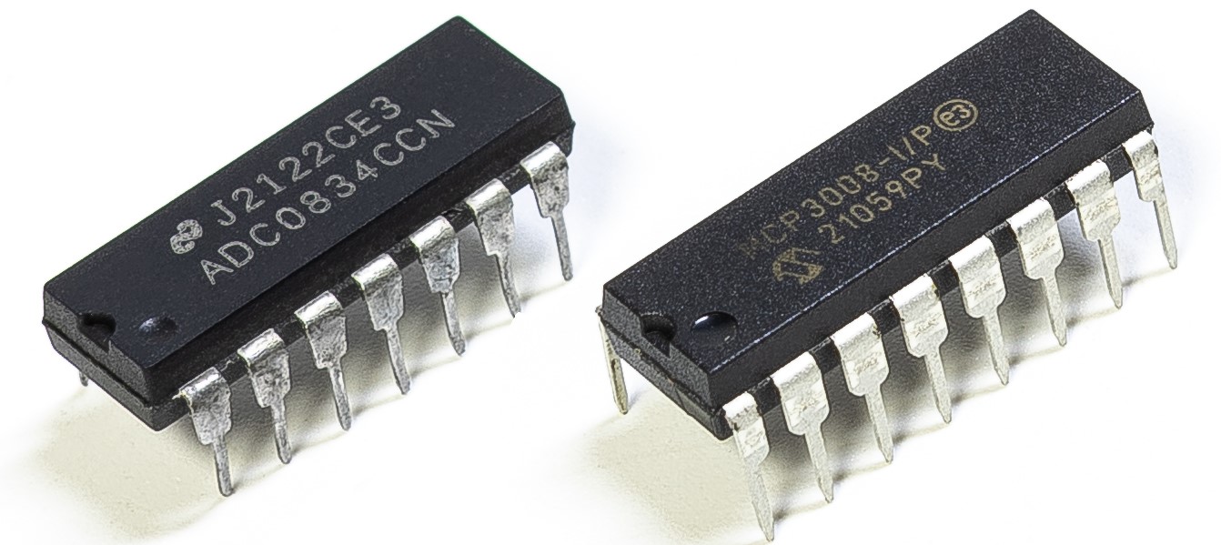
Depending on your kit version, please identify whether you have ADC0834 or MCP3008 and proceed with the matching section.
Introduction
Photoresistor is a commonly used component of ambient light intensity in life. It helps the controller to recognize day and night and realize light control functions such as night lamp. This project is very similar to potentiometer, and you might think it changing the voltage to sensing light.
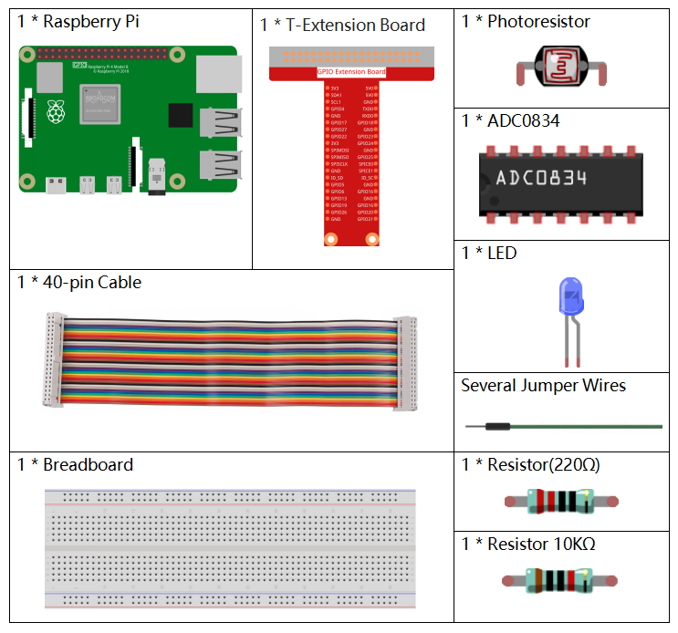
Components
Principle
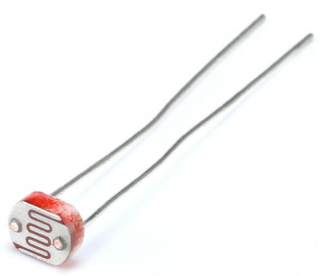
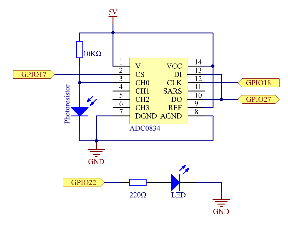
A photoresistor or photocell is a light-controlled variable resistor. The resistance of a photoresistor decreases with increasing incident light intensity; in other words, it exhibits photo conductivity. A photoresistor can be applied in light-sensitive detector circuits, and light- and darkness-activated switching circuits.
Schematic Diagram
Experimental Procedures
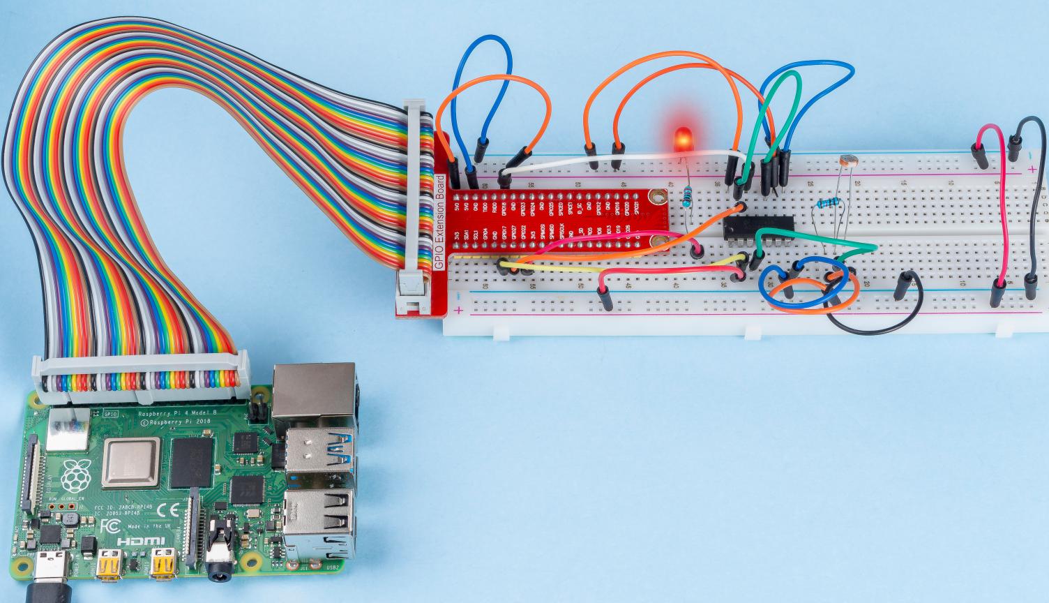
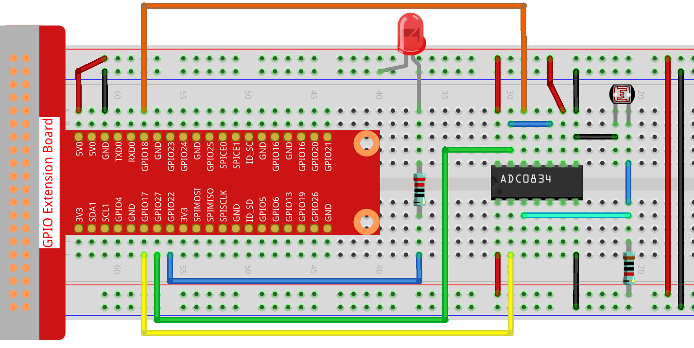
Step 1: Build the circuit.
For C Language Users
Step 2: Go to the folder of the code.
cd ~/davinci-kit-for-raspberry-pi/c/2.2.1/
Step 3: Compile the code.
gcc 2.2.1_Photoresistor.c -lwiringPi
Step 4: Run the executable file.
sudo ./a.out
The code run, the brightness of LED will vary depending on the intensity of light that the photoresistor senses.
Note
If it does not work after running, or there is an error prompt: "wiringPi.h: No such file or directory", please refer to Install and Check the WiringPi.
Code
#include <wiringPi.h>
#include <stdio.h>
#include <softPwm.h>
typedef unsigned char uchar;
typedef unsigned int uint;
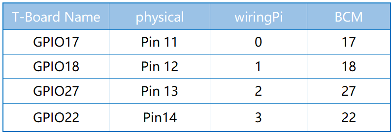
#define ADC_CS 0
#define ADC_CLK 1
#define ADC_DIO 2
#define LedPin 3
uchar get_ADC_Result(uint channel)
{
uchar i;
uchar dat1=0, dat2=0;
int sel = channel > 1 & 1;
int odd = channel & 1;
digitalWrite(ADC_CLK, 1);
delayMicroseconds(2);
digitalWrite(ADC_CLK, 0);
delayMicroseconds(2);
pinMode(ADC_DIO, OUTPUT);
digitalWrite(ADC_CS, 0);
// Start bit
digitalWrite(ADC_CLK,0);
digitalWrite(ADC_DIO,1); delayMicroseconds(2);
digitalWrite(ADC_CLK,1); delayMicroseconds(2);
//Single End mode
digitalWrite(ADC_CLK,0);
digitalWrite(ADC_DIO,1); delayMicroseconds(2);
digitalWrite(ADC_CLK,1); delayMicroseconds(2);
// ODD
digitalWrite(ADC_CLK,0);
digitalWrite(ADC_DIO,odd); delayMicroseconds(2);
digitalWrite(ADC_CLK,1); delayMicroseconds(2);
//Select
digitalWrite(ADC_CLK,0);
digitalWrite(ADC_DIO,sel); delayMicroseconds(2);
digitalWrite(ADC_CLK,1);
digitalWrite(ADC_DIO,1); delayMicroseconds(2);
digitalWrite(ADC_CLK,0);
digitalWrite(ADC_DIO,1); delayMicroseconds(2);
for(i=0;i<8;i++)
{
digitalWrite(ADC_CLK,1); delayMicroseconds(2);
digitalWrite(ADC_CLK,0); delayMicroseconds(2);
pinMode(ADC_DIO, INPUT);
dat1=dat1<<1 | digitalRead(ADC_DIO);
}
for(i=0;i<8;i++)
{
dat2 = dat2 | ((uchar)(digitalRead(ADC_DIO))<<i);
digitalWrite(ADC_CLK,1); delayMicroseconds(2);
digitalWrite(ADC_CLK,0); delayMicroseconds(2);
}
digitalWrite(ADC_CS,1);
pinMode(ADC_DIO, OUTPUT);
return(dat1==dat2) ? dat1 : 0;
}
int main(void)
{
uchar analogVal;
if(wiringPiSetup() == -1){ //when initialize wiring failed,print messageto screen
printf("setup wiringPi failed !");
return 1;
}
softPwmCreate(LedPin, 0, 100);
pinMode(ADC_CS, OUTPUT);
pinMode(ADC_CLK, OUTPUT);
while(1){
analogVal = get_ADC_Result(0);
printf("Current analogVal : %d\n", analogVal);
delay(100);
softPwmWrite(LedPin, analogVal);
delay(100);
}
return 0;
}
Code Explanation
The codes here are the same as that in 2.1.4 Potentiometer. If you have any other questions, please check the code explanation of 2.1.4 Potentiometer.c for details.
For Python Language Users
Step 2: Go to the folder of the code.
cd ~/davinci-kit-for-raspberry-pi/python/
Step 3: Run the executable file.
sudo python3 2.2.1_Photoresistor.py
The code run, the brightness of LED will vary depending on the intensity of light that the photoresistor senses.
Code
Note
You can Modify/Reset/Copy/Run/Stop the code below. But before that, you need to go to source code path like davinci-kit-for-raspberry-pi/python.
import RPi.GPIO as GPIO
import ADC0834
import time

LedPin = 22

def setup():
    global led_val
    # Set the GPIO modes to BCM Numbering
    GPIO.setmode(GPIO.BCM)
    # Set all LedPin's mode to output and initial level to High(3.3v)
    GPIO.setup(LedPin, GPIO.OUT, initial=GPIO.HIGH)
    ADC0834.setup()
    # Set led as pwm channel and frequece to 2KHz
    led_val = GPIO.PWM(LedPin, 2000)

    # Set all begin with value 0
    led_val.start(0)

def destroy():
    # Stop all pwm channel
    led_val.stop()
    # Release resource
    GPIO.cleanup()

def loop():
    while True:
        analogVal = ADC0834.getResult()
        print ('analog value = %d' % analogVal)
        led_val.ChangeDutyCycle(analogVal*100/255)
        time.sleep(0.2)

if __name__ == '__main__':
    setup()
    try:
        loop()
    except KeyboardInterrupt: # When 'Ctrl+C' is pressed, the program destroy() will be executed.
        destroy()
Code Explanation
def loop():
    while True:
        analogVal = ADC0834.getResult()
        print ('analog value = %d' % analogVal)
        led_val.ChangeDutyCycle(analogVal*100/255)
        time.sleep(0.2)
Read the analog value of CH0 of ADC0834. By default, the function getResult() is used to read the value of CH0, so if you want to read other channels, please input 1, 2, or 3 into () of the function getResult(). Next, what you need is to print the value via the print function. Because the changing element is the duty cycle of LedPin, the computational formula, analogVal*100/255 is needed to convert analogVal into percentage. Finally, ChangeDutyCycle() is called to write the percentage into LedPin.
Phenomenon Picture