Note
Hello, welcome to the SunFounder Raspberry Pi & Arduino & ESP32 Enthusiasts Community on Facebook! Dive deeper into Raspberry Pi, Arduino, and ESP32 with fellow enthusiasts.
Why Join?
Expert Support: Solve post-sale issues and technical challenges with help from our community and team.
Learn & Share: Exchange tips and tutorials to enhance your skills.
Exclusive Previews: Get early access to new product announcements and sneak peeks.
Special Discounts: Enjoy exclusive discounts on our newest products.
Festive Promotions and Giveaways: Take part in giveaways and holiday promotions.
👉 Ready to explore and create with us? Click [here] and join today!
2.2.2 Thermistor(MCP3008)
Note
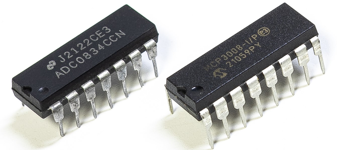
Depending on your kit version, please identify whether you have ADC0834 or MCP3008 and proceed with the matching section.
Introduction
Just like photoresistor can sense light, thermistor is a temperature sensitive electronic device that can be used for realizing functions of temperature control, such as making a heat alarm.
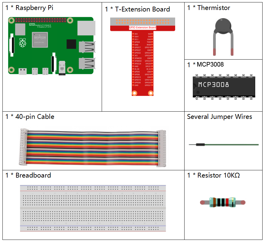
Required Components
In this project, we need the following components.
Principle
A thermistor is a thermally sensitive resistor that exhibits a precise and predictable change in resistance proportional to small changes in temperature. How much its resistance will change is dependent upon its unique composition. Thermistors are the parts of a larger group of passive components. And unlike their active component counterparts, passive devices are incapable of providing power gain, or amplification to a circuit.
Thermistor is a sensitive element, and it has two types: Negative Temperature Coefficient (NTC) and Positive Temperature Coefficient (PTC), also known as NTC and PTC. Its resistance varies significantly with temperature. The resistance of PTC thermistor increases with temperature ,while the condition of NTC is opposite to the former In this experiment we use NTC.

The principle is that the resistance of the NTC thermistor changes with the temperature of the outer environment. It detects the real-time temperature of the environment. When the temperature gets higher, the resistance of the thermistor decreases. Then the voltage data is converted to digital quantities by the A/D adapter. The temperature in Celsius or Fahrenheit is output via programming.
In this experiment, a thermistor and a 10k pull-up resistor are used. Each thermistor has a normal resistance. Here it is 10k ohm, which is measured under 25 degree Celsius.
Here is the relation between the resistance and temperature:
RT =RN expB(1/TK – 1/TN)
RT is the resistance of the NTC thermistor when the temperature is TK.
RN is the resistance of the NTC thermistor under the rated temperature TN. Here, the numerical value of RN is 10k.
TK is a Kelvin temperature and the unit is K. Here, the numerical value of TKis 273.15 + degree Celsius.
TN is a rated Kelvin temperature; the unit is K too. Here, the numerical value of TN is 273.15+25.
And B(beta), the material constant of NTC thermistor, is also called heat sensitivity index with a numerical value 3950.
exp is the abbreviation of exponential, and the base number e is a natural number and equals 2.7 approximately.
Convert this formula TK=1/(ln(RT/RN)/B+1/TN) to get Kelvin temperature that minus 273.15 equals degree Celsius.
This relation is an empirical formula. It is accurate only when the temperature and resistance are within the effective range.
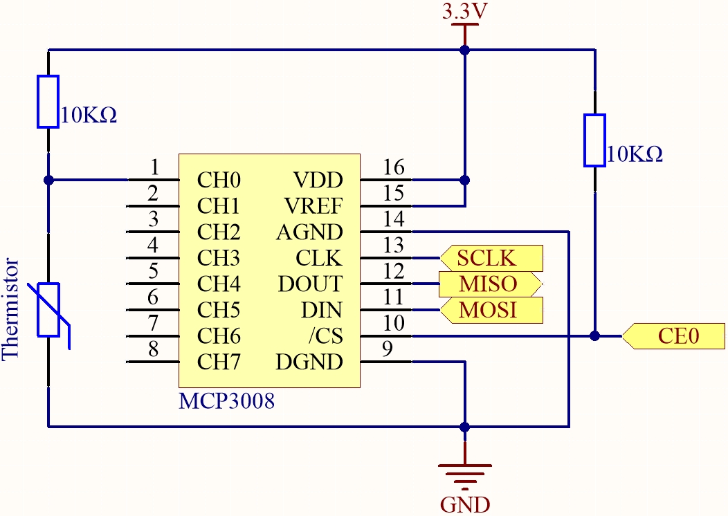
Schematic Diagram
T-Board Name |
physical |
WiringPi |
BCM |
|---|---|---|---|
SPICE0 |
pin24 |
10 |
8 |
SPIMOSI |
pin19 |
12 |
10 |
SPIMISO |
pin21 |
13 |
9 |
SPISCLK |
pin23 |
14 |
11 |
Experimental Procedures
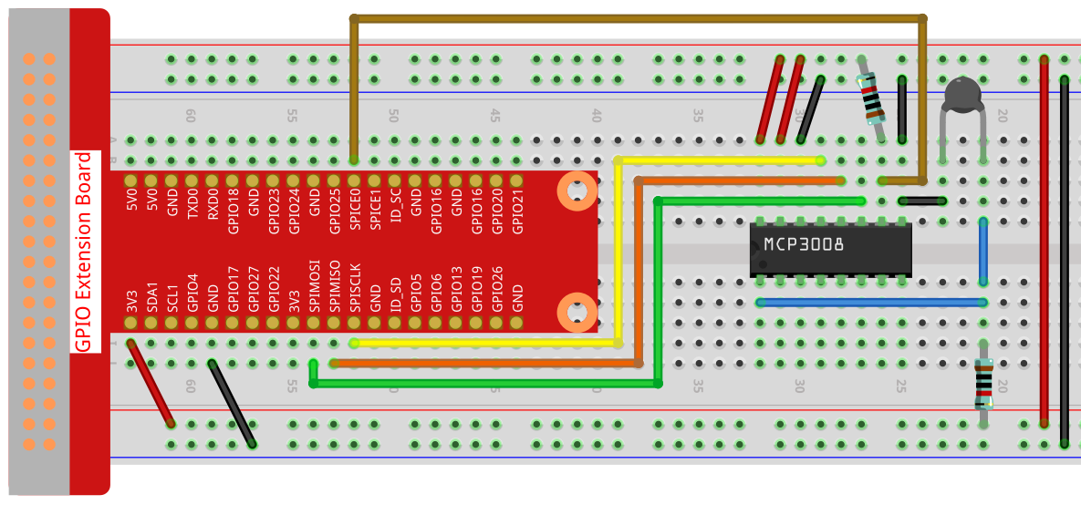
Step 1: Build the circuit.
For C Language Users
Step 2: Go to the folder of the code.
cd ~/davinci-kit-for-raspberry-pi/c/2.2.2-2/
Step 3: Compile the code.
gcc 2.2.2_Thermistor.c -o Thermistor -lwiringPi -lm
Note
-lm is to load the library math. Do not omit, or you will make an error.
Step 4: Run the executable file.
./Thermistor
With the code run, the thermistor detects ambient temperature which will be printed on the screen once it finishes the program calculation.
Note
If it does not work after running, or there is an error prompt: "wiringPi.h: No such file or directory", please refer to Install and Check the WiringPi.
Code
#include <wiringPi.h>
#include <wiringPiSPI.h>
#include <stdio.h>
#include <math.h>

#define SPI_CHANNEL 0  // CE0
#define SPI_SPEED   1000000  // 1MHz

int read_ADC(int channel) {
    if (channel < 0 || channel > 7) return -1;

    unsigned char buffer[3];
    buffer[0] = 1;  // Start bit
    buffer[1] = (8 + channel) << 4;  // Single-ended mode + channel
    buffer[2] = 0;

    wiringPiSPIDataRW(SPI_CHANNEL, buffer, 3);

    int value = ((buffer[1] & 3) << 8) | buffer[2];
    return value;
}

int main(void) {
    int analogVal;
    double Vr, Rt, temp, cel, Fah;

    if (wiringPiSetup() == -1) {
        printf("setup wiringPi failed!\n");
        return 1;
    }

    if (wiringPiSPISetup(SPI_CHANNEL, SPI_SPEED) == -1) {
        printf("SPI setup failed!\n");
        return 1;
    }

    while (1) {
        analogVal = read_ADC(0);  // Read from CH0

        // MCP3008 is 10-bit ADC (0–1023)
        Vr = 3.3 * analogVal / 1023.0;  // Assume Vref = 3.3V
        Rt = 10000.0 * Vr / (3.3 - Vr); // Voltage divider, 10k resistor
        temp = 1 / ((log(Rt / 10000.0) / 3950.0) + (1 / (273.15 + 25.0)));
        cel = temp - 273.15;
        Fah = cel * 1.8 + 32;

        printf("Celsius: %.2f C  Fahrenheit: %.2f F\n", cel, Fah);
        delay(1000);
    }

    return 0;
}
Code Explanation
#include <wiringPi.h>
#include <wiringPiSPI.h>
#include <stdio.h>
#include <math.h>
These header files include libraries for GPIO control (wiringPi.h), SPI communication (wiringPiSPI.h), standard I/O operations (stdio.h), and math functions (math.h) in C.
#define SPI_CHANNEL 0
#define SPI_SPEED   1000000
Define constants for the SPI channel and SPI communication speed. Here, SPI channel 0 (CE0) and a clock speed of 1 MHz are used.
int read_ADC(int channel)
This function reads analog data from a specified channel of the MCP3008 ADC.
buffer[0] = 1;
buffer[1] = (8 + channel) << 4;
buffer[2] = 0;
These lines format the SPI command according to the MCP3008 protocol: a start bit, configuration for single-ended mode, and the channel number.
wiringPiSPIDataRW(SPI_CHANNEL, buffer, 3);
Transfer the SPI command and receive the 10-bit ADC data from MCP3008.
int value = ((buffer[1] & 3) << 8) | buffer[2];
Extract and combine the 10-bit ADC result from the returned SPI buffer.
if (wiringPiSetup() == -1) { ... }
if (wiringPiSPISetup(SPI_CHANNEL, SPI_SPEED) == -1) { ... }
These lines initialize WiringPi and configure SPI. If initialization fails, the program exits.
analogVal = read_ADC(0);
Reads the analog signal from MCP3008 channel 0, where the thermistor voltage divider is connected.
Vr = 3.3 * analogVal / 1023.0;
Convert the digital ADC value into an analog voltage. The ADC range is 0–1023 with 3.3V reference voltage.
Rt = 10000.0 * Vr / (3.3 - Vr);
Calculate the resistance of the thermistor using the voltage divider formula. A 10kΩ resistor is assumed in series with the thermistor.
temp = 1 / ((log(Rt / 10000.0) / 3950.0) + (1 / (273.15 + 25.0)));
Use the B-parameter equation to convert the thermistor resistance to temperature in Kelvin.
T(K) = 1 / [ln(Rt/R₀)/B + 1/T₀], where - R₀ = 10kΩ - B = 3950 - T₀ = 25°C = 298.15K
cel = temp - 273.15;
Convert the temperature from Kelvin to degrees Celsius.
Fah = cel * 1.8 + 32;
Convert the Celsius temperature to Fahrenheit.
printf("Celsius: %.2f C Fahrenheit: %.2f F\n", cel, Fah);
Display the temperature in both Celsius and Fahrenheit on the terminal with 2 decimal places of precision.
For Python Language Users
Step 2: Set up the SPI interface and install the spidev library (see SPI Configuration for detailed instructions). If you have already completed these steps, you can skip this.
Step 3: Go to the folder of the code.
cd ~/davinci-kit-for-raspberry-pi/python
Step 4: Run the executable file
sudo python3 2.2.2-2_thermistor.py
With the code run, the thermistor detects ambient temperature which will be printed on the screen once it finishes the program calculation.
Warning
If there is an error prompt RuntimeError: Cannot determine SOC peripheral base address, please refer to If gpiozero doesn’t work.
Code
Note
You can Modify/Reset/Copy/Run/Stop the code below. But before that, you need to go to source code path like davinci-kit-for-raspberry-pi/python. After modifying the code, you can run it directly to see the effect.
#!/usr/bin/env python3
# -*- coding: utf-8 -*-

import spidev
import time
import math
import RPi.GPIO as GPIO

# Set GPIO mode
GPIO.setmode(GPIO.BCM)

# Initialize SPI for MCP3008 (Bus 0, CE0)
spi = spidev.SpiDev()
spi.open(0, 0)  # Bus 0, Device 0 (CE0)
spi.max_speed_hz = 1000000  # 1 MHz

def read_adc(channel):
    """
    Read analog value from MCP3008 channel (0–7)
    """
    if channel < 0 or channel > 7:
        return -1
    adc = spi.xfer2([1, (8 + channel) << 4, 0])
    value = ((adc[1] & 0x03) << 8) | adc[2]
    return value

try:
    while True:
        # Read analog value from CH0 of MCP3008
        analogVal = read_adc(0)

        # Convert to voltage (assuming 3.3V reference)
        Vr = 3.3 * analogVal / 1023.0

        # Calculate thermistor resistance (R2 in voltage divider is 10kΩ)
        Rt = 10000.0 * Vr / (3.3 - Vr)

        # Steinhart–Hart calculation
        tempK = 1.0 / (((math.log(Rt / 10000.0)) / 3950.0) + (1.0 / (273.15 + 25.0)))

        # Convert to Celsius and Fahrenheit
        Cel = tempK - 273.15
        Fah = Cel * 1.8 + 32

        # Print the result
        print('Celsius: %.2f °C  Fahrenheit: %.2f °F' % (Cel, Fah))

        time.sleep(0.2)

except KeyboardInterrupt:
    pass

finally:
    spi.close()
    GPIO.cleanup()
Code Explanation
This section imports required libraries:
spidevfor SPI communication with MCP3008timefor delay functionalitymathfor logarithmic operations in the Steinhart–Hart temperature formulaRPi.GPIOfor initializing and cleaning up GPIO (included for structural completeness)
#!/usr/bin/env python3
# -*- coding: utf-8 -*-

import spidev
import time
import math
import RPi.GPIO as GPIO
Initializes the GPIO mode as BCM and configures the SPI interface on bus 0 and device 0 (CE0), with a speed of 1 MHz.
# Set GPIO mode
GPIO.setmode(GPIO.BCM)

# Initialize SPI for MCP3008 (Bus 0, CE0)
spi = spidev.SpiDev()
spi.open(0, 0)  # Bus 0, Device 0 (CE0)
spi.max_speed_hz = 1000000  # 1 MHz
Defines a function
read_adc(channel)to read analog values from a specified MCP3008 channel (0–7). It sends a 3-byte SPI command and receives a 10-bit analog result (0–1023).def read_adc(channel): """ Read analog value from MCP3008 channel (0–7) """ if channel < 0 or channel > 7: return -1 adc = spi.xfer2([1, (8 + channel) << 4, 0]) value = ((adc[1] & 0x03) << 8) | adc[2] return value
Main loop: Reads analog voltage from a thermistor on channel 0, converts it to resistance, then uses the Steinhart–Hart equation to estimate temperature in Celsius and Fahrenheit. Updates are printed every 0.2 seconds.
try:
    while True:
        # Read analog value from CH0 of MCP3008
        analogVal = read_adc(0)

        # Convert to voltage (assuming 3.3V reference)
        Vr = 3.3 * analogVal / 1023.0

        # Calculate thermistor resistance (R2 in voltage divider is 10kΩ)
        Rt = 10000.0 * Vr / (3.3 - Vr)

        # Steinhart–Hart calculation
        tempK = 1.0 / (((math.log(Rt / 10000.0)) / 3950.0) + (1.0 / (273.15 + 25.0)))

        # Convert to Celsius and Fahrenheit
        Cel = tempK - 273.15
        Fah = Cel * 1.8 + 32

        # Print the result
        print('Celsius: %.2f °C  Fahrenheit: %.2f °F' % (Cel, Fah))

        time.sleep(0.2)
The
finallyblock ensures graceful shutdown. It closes the SPI interface and performs GPIO cleanup to release all hardware resources.except KeyboardInterrupt: pass finally: spi.close() GPIO.cleanup()