Note
Hello, welcome to the SunFounder Raspberry Pi & Arduino & ESP32 Enthusiasts Community on Facebook! Dive deeper into Raspberry Pi, Arduino, and ESP32 with fellow enthusiasts.
Why Join?
Expert Support: Solve post-sale issues and technical challenges with help from our community and team.
Learn & Share: Exchange tips and tutorials to enhance your skills.
Exclusive Previews: Get early access to new product announcements and sneak peeks.
Special Discounts: Enjoy exclusive discounts on our newest products.
Festive Promotions and Giveaways: Take part in giveaways and holiday promotions.
👉 Ready to explore and create with us? Click [here] and join today!
2.1.6 Joystick(MCP3008)
Note
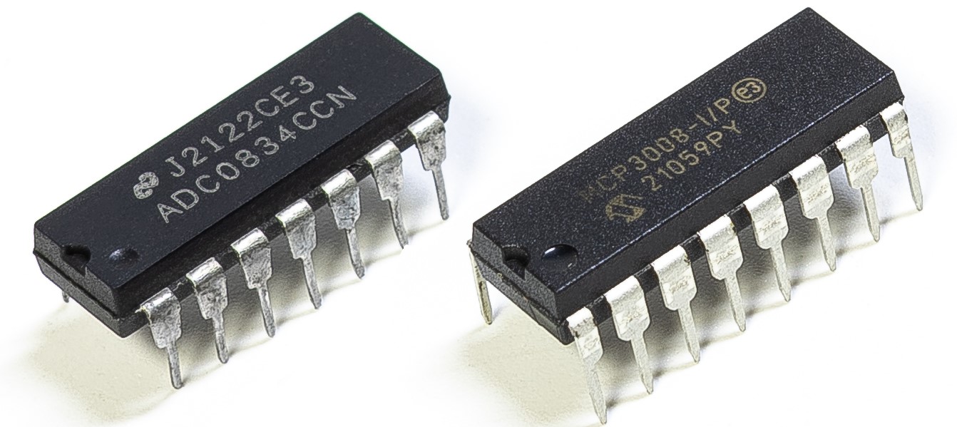
Depending on your kit version, please identify whether you have ADC0834 or MCP3008 and proceed with the matching section.
Introduction
In this project, We’re going to learn how joystick works. We manipulate the Joystick and display the results on the screen.
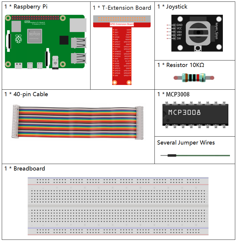
Required Components
In this project, we need the following components.
Principle
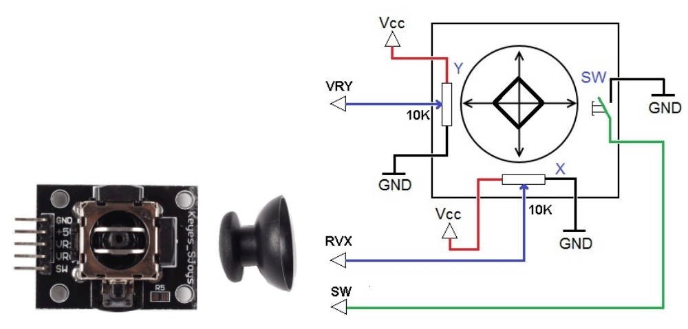
Joystick
The basic idea of a joystick is to translate the movement of a stick into electronic information that a computer can process.
In order to communicate a full range of motion to the computer, a joystick needs to measure the stick’s position on two axes – the X-axis (left to right) and the Y-axis (up and down). Just as in basic geometry, the X-Y coordinates pinpoint the stick’s position exactly.
To determine the location of the stick, the joystick control system simply monitors the position of each shaft. The conventional analog joystick design does this with two potentiometers, or variable resistors.
The joystick also has a digital input that is actuated when the joystick is pressed down.
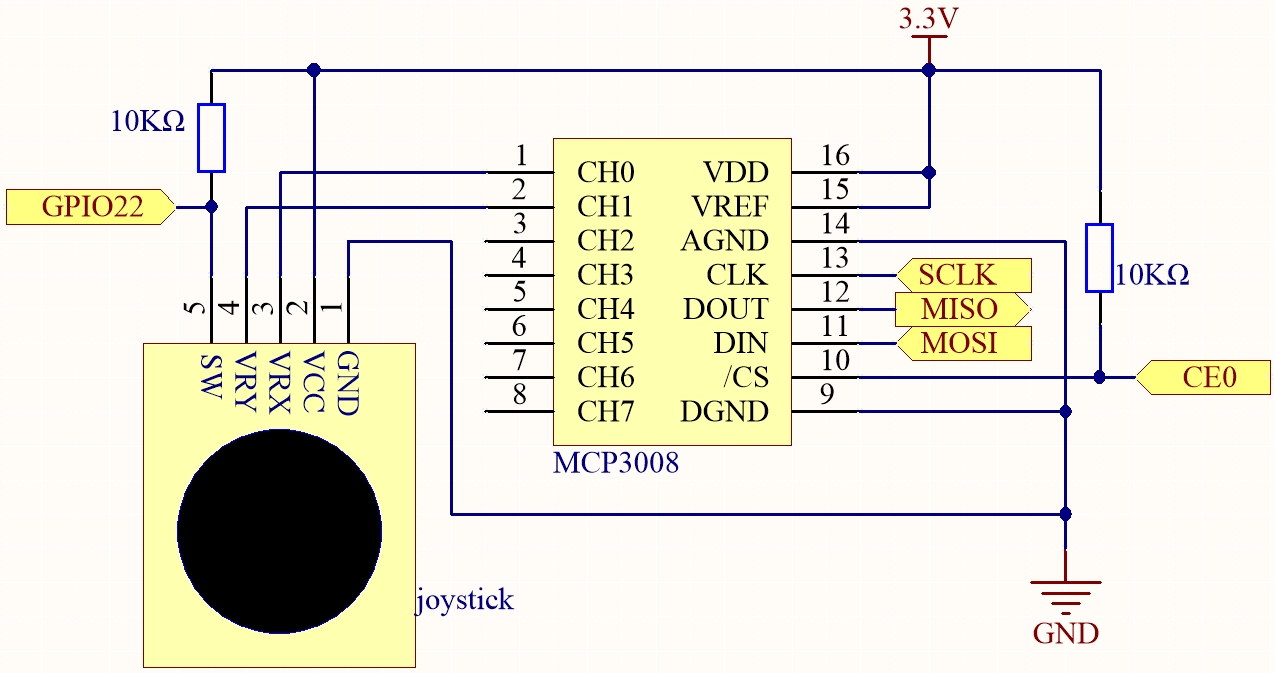
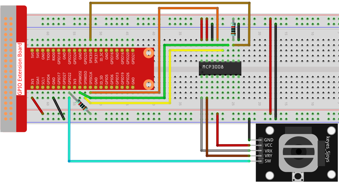
Schematic Diagram
When the data of joystick is read, there are some differents between axis: data of X and Y axis is analog, which need to use MCP3008 to convert the analog value to digital value. Data of Z axis is digital, so you can directly use the GPIO to read, or you can also use ADC to read.
Experimental Procedures
Step 1: Build the circuit.
For C Language Users
Step 2: Go to the folder of the code.
cd ~/davinci-kit-for-raspberry-pi/c/2.1.6-2/
Step 3: Compile the code.
gcc 2.1.6_Joystick.c -o joystick -lwiringPi
Step 4: Run the executable file.
./joystick
After the code runs, turn the Joystick, then the corresponding values of x, y, Btn are displayed on screen.
Note
If it does not work after running, or there is an error prompt: "wiringPi.h: No such file or directory", please refer to Install and Check the WiringPi.
Code
#include <wiringPi.h>
#include <wiringPiSPI.h>
#include <stdio.h>

#define SPI_CHANNEL 0
#define SPI_SPEED   1000000  // 1 MHz
#define BtnPin      3        // WiringPi 3 = BCM GPIO22

// Read from MCP3008 channel (0–7)
int read_ADC(int channel) {
    if (channel < 0 || channel > 7) return -1;

    unsigned char buffer[3];
    buffer[0] = 1;                            // Start bit
    buffer[1] = (8 + channel) << 4;           // Channel config
    buffer[2] = 0;

    wiringPiSPIDataRW(SPI_CHANNEL, buffer, 3);

    int result = ((buffer[1] & 0x03) << 8) | buffer[2];
    return result;
}

int main(void) {
    if (wiringPiSetup() == -1) {
        printf("WiringPi setup failed!\n");
        return 1;
    }

    if (wiringPiSPISetup(SPI_CHANNEL, SPI_SPEED) == -1) {
        printf("SPI setup failed!\n");
        return 1;
    }

    pinMode(BtnPin, INPUT);
    pullUpDnControl(BtnPin, PUD_UP);

    while (1) {
        int x_val = read_ADC(0);     // VRX on CH0
        int y_val = read_ADC(1);     // VRY on CH1
        int btn_val = digitalRead(BtnPin);  // SW button

        printf("x = %d, y = %d, btn = %d\n", x_val, y_val, btn_val);
        delay(100);
    }

    return 0;
}
Code Explanation
This section initializes the libraries needed for GPIO and SPI communication.
#include <wiringPi.h>
#include <wiringPiSPI.h>
#include <stdio.h>

#define SPI_CHANNEL 0
#define SPI_SPEED   1000000  // 1 MHz
#define BtnPin      3        // WiringPi 3 = BCM GPIO22
Defines a function read_ADC() to read analog data from MCP3008. It communicates over SPI to request data from a given channel (0–7), then parses the response to get a 10-bit ADC result.
int read_ADC(int channel) {
    if (channel < 0 || channel > 7) return -1;

    unsigned char buffer[3];
    buffer[0] = 1;
    buffer[1] = (8 + channel) << 4;
    buffer[2] = 0;

    wiringPiSPIDataRW(SPI_CHANNEL, buffer, 3);

    int result = ((buffer[1] & 0x03) << 8) | buffer[2];
    return result;
}
The main function initializes the WiringPi and SPI interfaces, configures the joystick’s button pin, and continuously reads joystick values and prints them to the console.
int main(void) {
    if (wiringPiSetup() == -1) {
        printf("WiringPi setup failed!\n");
        return 1;
    }

    if (wiringPiSPISetup(SPI_CHANNEL, SPI_SPEED) == -1) {
        printf("SPI setup failed!\n");
        return 1;
    }

    pinMode(BtnPin, INPUT);
    pullUpDnControl(BtnPin, PUD_UP);

    while (1) {
        int x_val = read_ADC(0);     // VRX to CH0
        int y_val = read_ADC(1);     // VRY to CH1
        int btn_val = digitalRead(BtnPin);  // SW to GPIO22

        printf("x = %d, y = %d, btn = %d\n", x_val, y_val, btn_val);
        delay(100);
    }

    return 0;
}
For Python Language Users
Step 2: Set up the SPI interface and install the spidev library (see SPI Configuration for detailed instructions). If you have already completed these steps, you can skip this.
Step 3: Go to the folder of the code.
cd ~/davinci-kit-for-raspberry-pi/python
Step 4: Run.
sudo python3 2.1.6-2_Joystick.py
After the code runs, turn the Joystick, then the corresponding values of x, y, Btn are displayed on screen.
Warning
If there is an error prompt RuntimeError: Cannot determine SOC peripheral base address, please refer to If gpiozero doesn’t work.
Code
Note
You can Modify/Reset/Copy/Run/Stop the code below. But before that, you need to go to source code path like davinci-kit-for-raspberry-pi/python. After modifying the code, you can run it directly to see the effect.
#!/usr/bin/env python3

import RPi.GPIO as GPIO
import spidev
import time

# Define GPIO pin for joystick button (SW pin)
BTN_PIN = 22

# Set up GPIO mode
GPIO.setmode(GPIO.BCM)
GPIO.setup(BTN_PIN, GPIO.IN, pull_up_down=GPIO.PUD_UP)  # Use internal pull-up

# Initialize SPI communication with MCP3008
spi = spidev.SpiDev()
spi.open(0, 0)  # SPI bus 0, CE0
spi.max_speed_hz = 1000000  # 1 MHz

def read_adc(channel):
    """
    Reads analog value from the specified MCP3008 channel (0–7)
    :param channel: ADC channel number (0–7)
    :return: 10-bit integer value (0–1023)
    """
    if channel < 0 or channel > 7:
        return -1
    adc = spi.xfer2([1, (8 + channel) << 4, 0])
    value = ((adc[1] & 0x03) << 8) | adc[2]
    return value

try:
    # Main loop to read and print joystick values and button state
    while True:
        # Read X and Y values from MCP3008 channels 1 and 2
        x_val = read_adc(1)  # Joystick VRX connected to CH1
        y_val = read_adc(2)  # Joystick VRY connected to CH2

        # Read the state of the joystick button (SW)
        Btn_val = GPIO.input(BTN_PIN)  # 0 = pressed, 1 = released

        # Print the read values
        print('X: %d  Y: %d  Btn: %d' % (x_val, y_val, Btn_val))

        time.sleep(0.2)

except KeyboardInterrupt:
    pass

finally:
    spi.close()
    GPIO.cleanup()
Code Explanation
#!/usr/bin/env python3

import RPi.GPIO as GPIO
import spidev
import time
This section imports the required libraries:
RPi.GPIOis used to handle GPIO input (joystick button).spidevis used to communicate with the MCP3008 ADC chip via SPI.timeis used to introduce delays between readings.
# Define GPIO pin for joystick button (SW pin)
BTN_PIN = 22

# Set up GPIO mode
GPIO.setmode(GPIO.BCM)
GPIO.setup(BTN_PIN, GPIO.IN, pull_up_down=GPIO.PUD_UP)

# Initialize SPI communication with MCP3008
spi = spidev.SpiDev()
spi.open(0, 0)  # SPI bus 0, CE0
spi.max_speed_hz = 1000000
This block sets the GPIO mode to BCM, initializes the joystick button input on GPIO22 with a pull-up resistor, and configures the SPI interface with MCP3008 using bus 0 and chip enable 0 (CE0) at 1 MHz.
def read_adc(channel):
    """
    Reads analog value from the specified MCP3008 channel (0–7)
    :param channel: ADC channel number (0–7)
    :return: 10-bit integer value (0–1023)
    """
    if channel < 0 or channel > 7:
        return -1
    adc = spi.xfer2([1, (8 + channel) << 4, 0])
    value = ((adc[1] & 0x03) << 8) | adc[2]
    return value
Defines the read_adc() function to read analog data from a specific MCP3008 channel. It sends three bytes over SPI and interprets the response to return a 10-bit value from 0 to 1023.
try:
    # Main loop to read and print joystick values and button state
    while True:
        # Read X and Y values from MCP3008 channels 0 and 1
        x_val = read_adc(0)  # Joystick VRX connected to CH0
        y_val = read_adc(1)  # Joystick VRY connected to CH1

        # Read the state of the joystick button (SW)
        Btn_val = GPIO.input(BTN_PIN)  # 0 = pressed, 1 = released

        # Print the read values
        print('X: %d  Y: %d  Btn: %d' % (x_val, y_val, Btn_val))

        time.sleep(0.2)

except KeyboardInterrupt:
    pass

finally:
    spi.close()
    GPIO.cleanup()
This main loop reads and prints the X/Y analog positions from the joystick and its button state every 200ms. If the script is interrupted via keyboard (Ctrl+C), SPI and GPIO are properly cleaned up.