Note
Hello, welcome to the SunFounder Raspberry Pi & Arduino & ESP32 Enthusiasts Community on Facebook! Dive deeper into Raspberry Pi, Arduino, and ESP32 with fellow enthusiasts.
Why Join?
Expert Support: Solve post-sale issues and technical challenges with help from our community and team.
Learn & Share: Exchange tips and tutorials to enhance your skills.
Exclusive Previews: Get early access to new product announcements and sneak peeks.
Special Discounts: Enjoy exclusive discounts on our newest products.
Festive Promotions and Giveaways: Take part in giveaways and holiday promotions.
👉 Ready to explore and create with us? Click [here] and join today!
2.2.1 Photoresistor
Note

Depending on your kit version, please identify whether you have ADC0834 or MCP3008 and proceed with the matching section.
Introduction
Photoresistor is a commonly used component of ambient light intensity in life. It helps the controller to recognize day and night and realize light control functions such as night lamp. This project is very similar to potentiometer, and you might think it changing the voltage to sensing light.
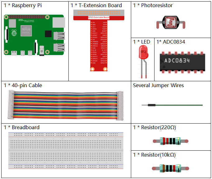
Required Components
In this project, we need the following components.
It’s definitely convenient to buy a whole kit, here’s the link:
Name |
ITEMS IN THIS KIT |
LINK |
|---|---|---|
Raphael Kit |
337 |
You can also buy them separately from the links below.
COMPONENT INTRODUCTION |
PURCHASE LINK |
|---|---|
- |
|
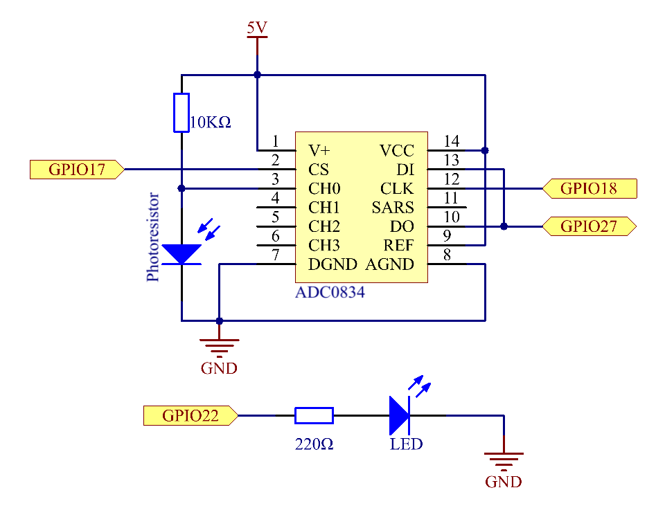
Schematic Diagram
Experimental Procedures
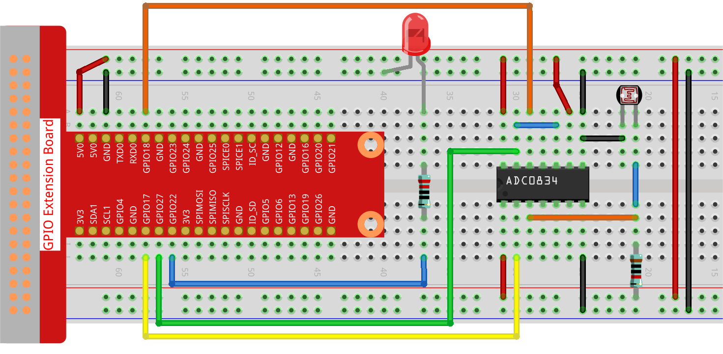
Step 1: Build the circuit.
Step 2: Go to the folder of the code.
cd ~/raphael-kit/python-pi5
Step 3: Run the executable file.
sudo python3 2.2.1_Photoresistor_zero.py
When the code is running, the brightness of the LED will change according to the light intensity sensed by the photoresistor.
Warning
If there is an error prompt RuntimeError: Cannot determine SOC peripheral base address, please refer to If gpiozero doesn’t work.
Code
Note
You can Modify/Reset/Copy/Run/Stop the code below. But before that, you need to go to source code path like raphael-kit/python-pi5. After modifying the code, you can run it directly to see the effect.
 #!/usr/bin/env python3
 from gpiozero import PWMLED
import ADC0834
import time

 # Initialize a PWM LED on GPIO pin 22
 led = PWMLED(22)

# Set up the ADC0834 module
ADC0834.setup()

 # Define a function for mapping values from one range to another
 def MAP(x, in_min, in_max, out_min, out_max):
     return (x - in_min) * (out_max - out_min) / (in_max - in_min) + out_min

 # Main loop for reading ADC value and controlling LED brightness
 def loop():
     while True:
        # Read analog value from ADC
        analogVal = ADC0834.getResult()
         print('value = %d' % analogVal)

        # Map the ADC value to a PWM value and set LED brightness
        led.value = float(analogVal/255)

         # Wait for 0.2 seconds
         time.sleep(0.2)

 # Run the main loop and handle KeyboardInterrupt for graceful shutdown
 try:
     loop()
 except KeyboardInterrupt:
    # Turn off LED before exiting
    led.value = 0
Code Explanation
This segment imports the PWMLED class from the gpiozero library, necessary for controlling PWM LEDs. It also includes the ADC0834 module for interfacing with the analog-to-digital converter, and the time module for executing time-based functions such as sleep.
#!/usr/bin/env python3
from gpiozero import PWMLED
import ADC0834
import time
Initializes a PWM LED connected to GPIO pin 22 and sets up the ADC0834 module, preparing it for use in the project.
# Initialize a PWM LED on GPIO pin 22
led = PWMLED(22)

# Set up the ADC0834 module
ADC0834.setup()
Defines a function to map an input value from one range to another. This function is crucial for translating the ADC readings into a suitable range for PWM control.
# Define a function for mapping values from one range to another
def MAP(x, in_min, in_max, out_min, out_max):
    return (x - in_min) * (out_max - out_min) / (in_max - in_min) + out_min
This section contains a loop that continuously reads the analog value from the ADC0834, maps it to a corresponding PWM value, and adjusts the LED brightness. A brief delay (time.sleep(0.2)) is included to make the changes visible and to avoid overburdening the CPU.
# Main loop for reading ADC value and controlling LED brightness
def loop():
    while True:
        # Read analog value from ADC
        analogVal = ADC0834.getResult()
        print('value = %d' % analogVal)

        # Map the ADC value to a PWM value and set LED brightness
        led.value = float(analogVal/255)

        # Wait for 0.2 seconds
        time.sleep(0.2)
Executes the loop function and includes error handling for a graceful shutdown on KeyboardInterrupt. It ensures the LED is turned off when the program is stopped.
# Run the main loop and handle KeyboardInterrupt for graceful shutdown
try:
    loop()
except KeyboardInterrupt:
    # Turn off LED before exiting
    led.value = 0