Note
Hello, welcome to the SunFounder Raspberry Pi & Arduino & ESP32 Enthusiasts Community on Facebook! Dive deeper into Raspberry Pi, Arduino, and ESP32 with fellow enthusiasts.
Why Join?
Expert Support: Solve post-sale issues and technical challenges with help from our community and team.
Learn & Share: Exchange tips and tutorials to enhance your skills.
Exclusive Previews: Get early access to new product announcements and sneak peeks.
Special Discounts: Enjoy exclusive discounts on our newest products.
Festive Promotions and Giveaways: Take part in giveaways and holiday promotions.
👉 Ready to explore and create with us? Click [here] and join today!
2.2.6 Speed Sensor Module
Introduction
In this project, we will learn the use of the speed sensor module. A Speed sensor module is a type of tachometer that is used to measure the speed of a rotating object like a motor.
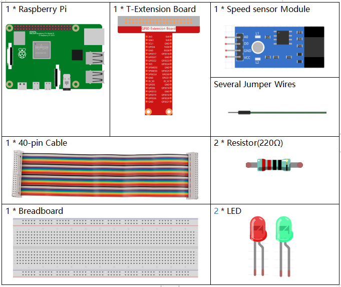
Required Components
In this project, we need the following components.
It’s definitely convenient to buy a whole kit, here’s the link:
Name |
ITEMS IN THIS KIT |
LINK |
|---|---|---|
Raphael Kit |
337 |
You can also buy them separately from the links below.
COMPONENT INTRODUCTION |
PURCHASE LINK |
|---|---|
- |
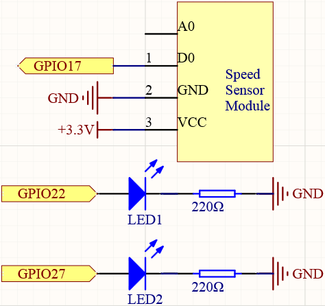
Schematic Diagram
Experimental Procedures
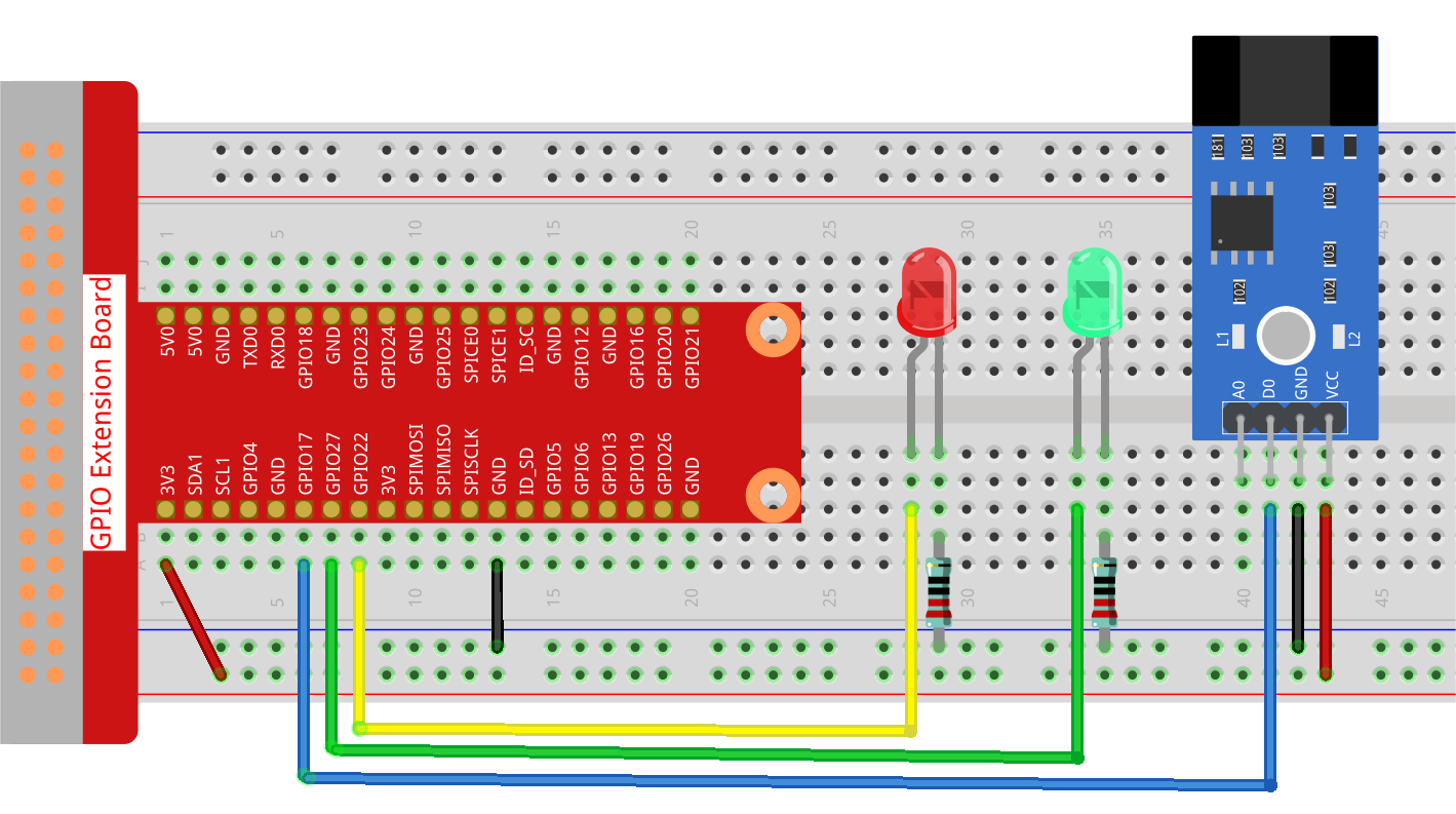
Step 1: Build the circuit.
Step 2: Change directory.
cd ~/raphael-kit/python-pi5
Step 3: Run.
sudo python3 2.2.6_speed_sensor_module_zero.py
After the code runs, the green LED will light up. If you place an obstacle in the gap of the speed sensor module, the “light blocked” will be printed on the screen and the red LED will be lit. Remove the obstacle and the green LED will light up again.
Warning
If there is an error prompt RuntimeError: Cannot determine SOC peripheral base address, please refer to If gpiozero doesn’t work.
Code
Note
You can Modify/Reset/Copy/Run/Stop the code below. But before that, you need to go to source code path like raphael-kit/python-pi5. After modifying the code, you can run it directly to see the effect.
#!/usr/bin/env python3
from gpiozero import LED, Button
from signal import pause

# Initialize GPIO pins for the speed sensor and LEDs using GPIO Zero library
speed_sensor = Button(17, pull_up=False)  # Speed sensor connected to GPIO pin 17 without pull-up
green_led = LED(27)                      # Green LED connected to GPIO pin 27
red_led = LED(22)                        # Red LED connected to GPIO pin 22

def update_leds():
    """
    Update the state of LEDs based on the speed sensor.
    - If the sensor is pressed (triggered), the red LED is turned on and a message is printed.
    - If the sensor is released (not triggered), the green LED is turned on.
    """
    if speed_sensor.is_pressed:
        green_led.off()  # Turn off green LED
        red_led.on()     # Turn on red LED
        print('Light was blocked')  # Print message indicating sensor is triggered
    else:
        green_led.on()   # Turn on green LED
        red_led.off()    # Turn off red LED

try:
    # Main loop to continuously check sensor state
    while True:
        # Update LEDs based on sensor state changes
        speed_sensor.when_pressed = update_leds   # Update LEDs when sensor is pressed
        speed_sensor.when_released = update_leds  # Update LEDs when sensor is released

except KeyboardInterrupt:
    # Handle KeyboardInterrupt (Ctrl+C) for a graceful script termination
    pass
Code Explanation
The
gpiozerolibrary is imported to use itsLEDandButtonclasses for interacting with the GPIO pins. Thesignallibrary is imported for thepausefunction, which is used to keep the script running.#!/usr/bin/env python3 from gpiozero import LED, Button from signal import pause
speed_sensor is set as a
Buttonon GPIO pin 17. Thepull_up=Falseparameter indicates that the internal pull-up resistor is not used.green_ledandred_ledare initialized asLEDobjects connected to GPIO pins 27 and 22, respectively.# Initialize GPIO pins for the speed sensor and LEDs using GPIO Zero library speed_sensor = Button(17, pull_up=False) # Speed sensor connected to GPIO pin 17 without pull-up green_led = LED(27) # Green LED connected to GPIO pin 27 red_led = LED(22) # Red LED connected to GPIO pin 22
The
update_ledsfunction checks the state of the speed sensor. If the sensor is pressed (activated), it turns off the green LED, turns on the red LED, and prints a message. If the sensor is released, it does the opposite.def update_leds(): """ Update the state of LEDs based on the speed sensor. - If the sensor is pressed (triggered), the red LED is turned on and a message is printed. - If the sensor is released (not triggered), the green LED is turned on. """ if speed_sensor.is_pressed: green_led.off() # Turn off green LED red_led.on() # Turn on red LED print('Light was blocked') # Print message indicating sensor is triggered else: green_led.on() # Turn on green LED red_led.off() # Turn off red LED
The main loop continuously checks the state of the speed sensor. The
when_pressedandwhen_releasedattributes are event handlers that call theupdate_ledsfunction when the sensor state changes. The try-except block is for handling a KeyboardInterrupt for a graceful exit.try: # Main loop to continuously check sensor state while True: # Update LEDs based on sensor state changes speed_sensor.when_pressed = update_leds # Update LEDs when sensor is pressed speed_sensor.when_released = update_leds # Update LEDs when sensor is released except KeyboardInterrupt: # Handle KeyboardInterrupt (Ctrl+C) for a graceful script termination pass