Note
Hello, welcome to the SunFounder Raspberry Pi & Arduino & ESP32 Enthusiasts Community on Facebook! Dive deeper into Raspberry Pi, Arduino, and ESP32 with fellow enthusiasts.
Why Join?
Expert Support: Solve post-sale issues and technical challenges with help from our community and team.
Learn & Share: Exchange tips and tutorials to enhance your skills.
Exclusive Previews: Get early access to new product announcements and sneak peeks.
Special Discounts: Enjoy exclusive discounts on our newest products.
Festive Promotions and Giveaways: Take part in giveaways and holiday promotions.
👉 Ready to explore and create with us? Click [here] and join today!
2.2.4 Reed Switch Module
Introduction
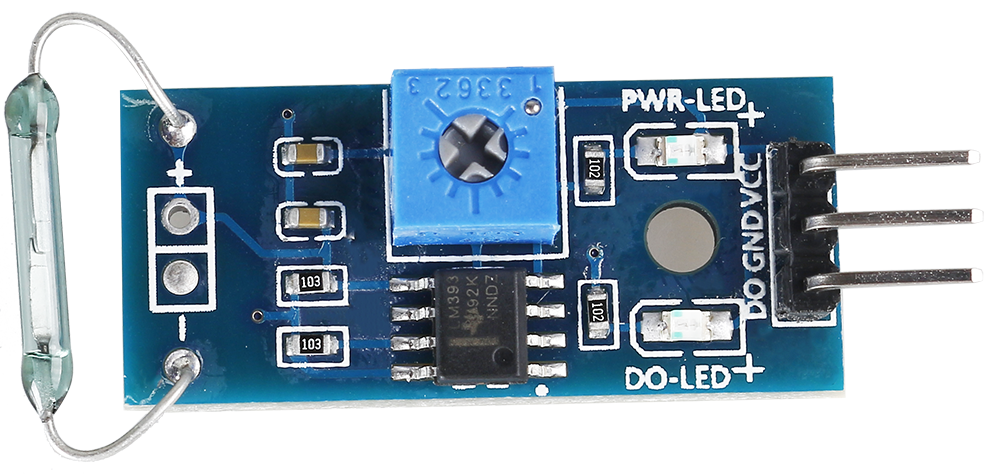
In this project, we will learn about the reed switch, which is an electrical switch that operates by means of an applied magnetic field.
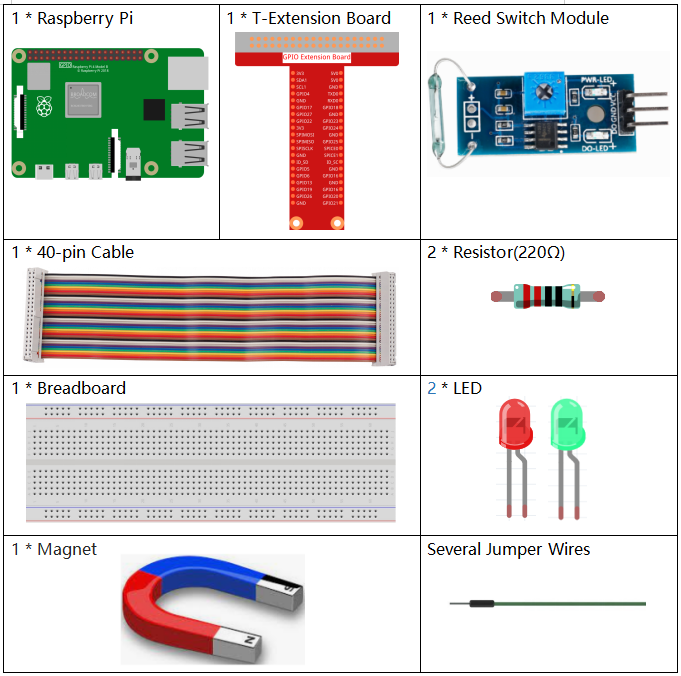
Required Components
In this project, we need the following components.
It’s definitely convenient to buy a whole kit, here’s the link:
Name |
ITEMS IN THIS KIT |
LINK |
|---|---|---|
Raphael Kit |
337 |
You can also buy them separately from the links below.
COMPONENT INTRODUCTION |
PURCHASE LINK |
|---|---|
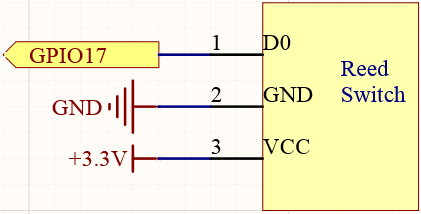
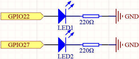
Schematic Diagram
T-Board Name |
physical |
wiringPi |
BCM |
GPIO17 |
Pin 11 |
0 |
17 |
GPIO27 |
Pin 13 |
2 |
27 |
GPIO22 |
Pin 15 |
3 |
22 |
Experimental Procedures
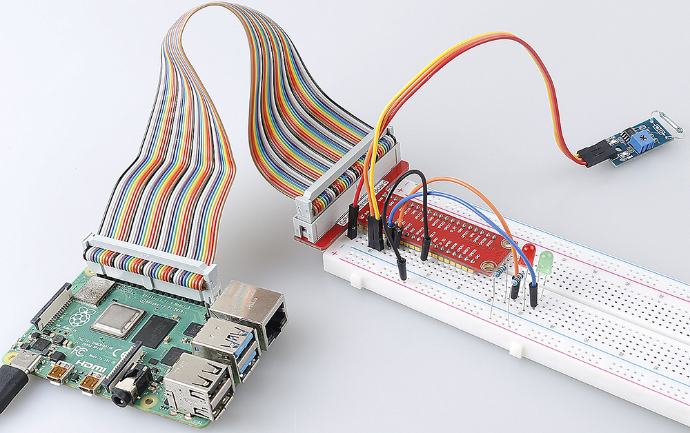
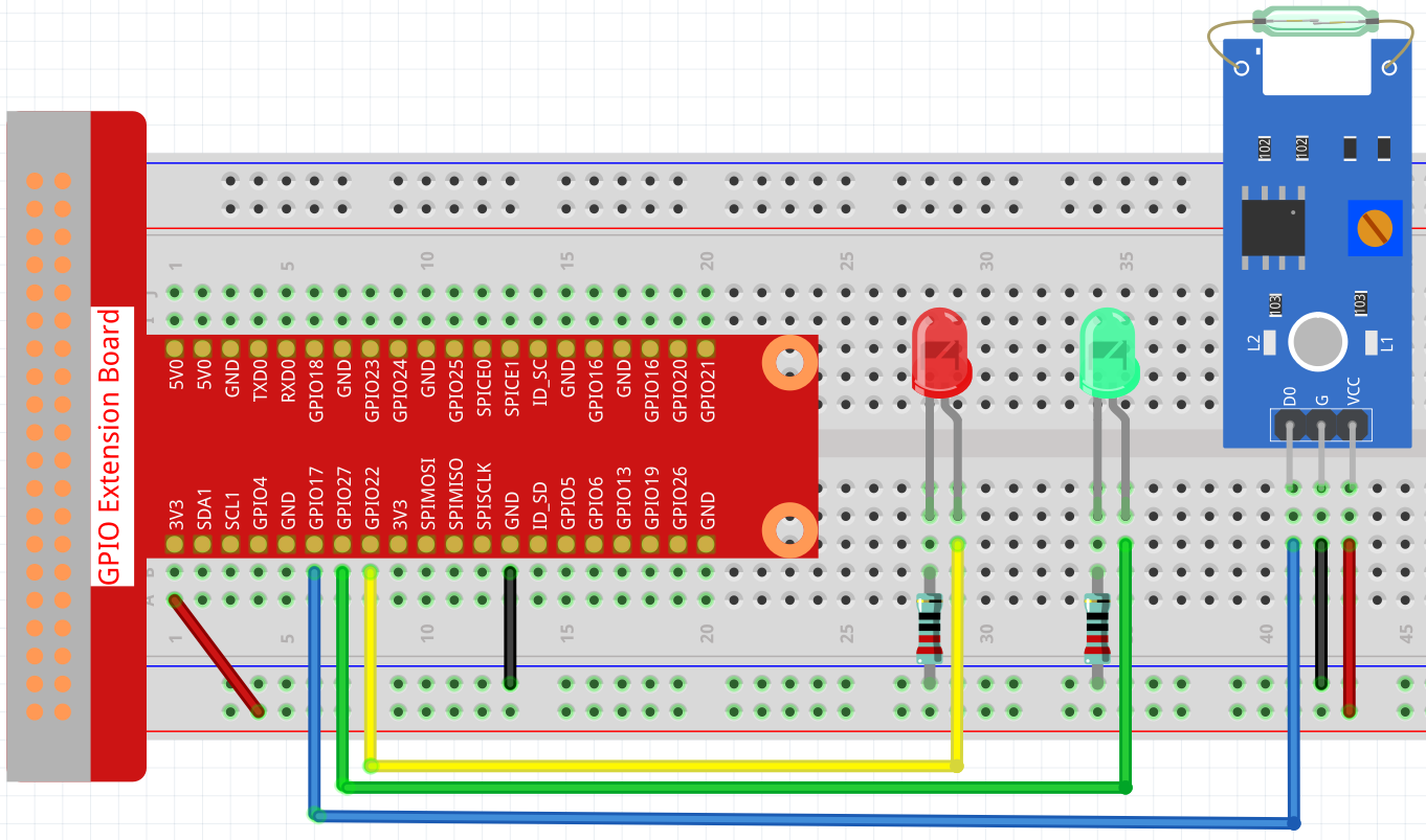
Step 1: Build the circuit.
Step 2: Change directory.
cd ~/raphael-kit/c/2.2.4/
Step 3: Compile.
gcc 2.2.4_ReedSwitch.c -lwiringPi
Step 4: Run.
sudo ./a.out
The green LED will light up when the code is run. If a magnet is placed close to the reed switch module, the red LED lights up; take away the magnet and the green LED lights up again.
Note
If it does not work after running, or there is an error prompt: "wiringPi.h: No such file or directory", please refer to Install and Check the WiringPi.
Code
#include <wiringPi.h>
#include <stdio.h>

#define ReedPin             0
#define Gpin                2
#define Rpin                3

void LED(char* color)
{
    pinMode(Gpin, OUTPUT);
    pinMode(Rpin, OUTPUT);
    if (color == "RED")
    {
        digitalWrite(Rpin, HIGH);
        digitalWrite(Gpin, LOW);
    }
    else if (color == "GREEN")
    {
        digitalWrite(Rpin, LOW);
        digitalWrite(Gpin, HIGH);
    }
    else
        printf("LED Error");
}

int main(void)
{
    if(wiringPiSetup() == -1){ //when initialize wiring failed,print messageto screen
        printf("setup wiringPi failed !");
        return 1;
    }

    pinMode(ReedPin, INPUT);
    LED("GREEN");

    while(1){
        if(0 == digitalRead(ReedPin)){
            delay(10);
            if(0 == digitalRead(ReedPin)){
                LED("RED");
                printf("Detected Magnetic Material!\n");
            }
        }
        else if(1 == digitalRead(ReedPin)){
            delay(10);
            if(1 == digitalRead(ReedPin)){
                while(!digitalRead(ReedPin));
                LED("GREEN");
            }
        }
    }
    return 0;
}
Code Explanation
#define ReedPin             0
#define Gpin                2
#define Rpin                3
Pin GPIO17, GPIO27 and GPIO22 of the T_Extension Board is corresponding to
the GPIO0, GPIO2 and GPIO3 in wiringPi. Assign GPIO0, GPIO2 and GPIO3 to
ReedPin, Gpin and Rpin.
void LED(char* color)
{
    pinMode(Gpin, OUTPUT);
    pinMode(Rpin, OUTPUT);
    if (color == "RED")
    {
        digitalWrite(Rpin, HIGH);
        digitalWrite(Gpin, LOW);
    }
    else if (color == "GREEN")
    {
        digitalWrite(Rpin, LOW);
        digitalWrite(Gpin, HIGH);
    }
    else
        printf("LED Error");
}
Set a LED() function to control the 2 LEDs, the parameter of this function is color.
When color is "RED", set Rpin to HIGH (light up the red LED) and Gpin to LOW (turn off the green LED); when color is "GREEN", then light up the green LED and turn off the red LED.
while(1){
        if(0 == digitalRead(ReedPin)){
            delay(10);
            if(0 == digitalRead(ReedPin)){
                LED("RED");
                printf("Detected Magnetic Material!\n");
            }
        }
        else if(1 == digitalRead(ReedPin)){
            delay(10);
            if(1 == digitalRead(ReedPin)){
                while(!digitalRead(ReedPin));
                LED("GREEN");
            }
        }
    }
Read the value of the reed switch module, if the value read 2 times is 0, call LED("RED") to light up the red LED and print "Magnetic material detected!".
If the value is 1, the green LED is lit.
Phenomenon Picture