Note
Hello, welcome to the SunFounder Raspberry Pi & Arduino & ESP32 Enthusiasts Community on Facebook! Dive deeper into Raspberry Pi, Arduino, and ESP32 with fellow enthusiasts.
Why Join?
Expert Support: Solve post-sale issues and technical challenges with help from our community and team.
Learn & Share: Exchange tips and tutorials to enhance your skills.
Exclusive Previews: Get early access to new product announcements and sneak peeks.
Special Discounts: Enjoy exclusive discounts on our newest products.
Festive Promotions and Giveaways: Take part in giveaways and holiday promotions.
👉 Ready to explore and create with us? Click [here] and join today!
2.2.6 Speed Sensor Module
Introduction
In this project, we will learn the use of the speed sensor module. A Speed Sensor Module is a type of tachometer that is used to measure the speed of a rotating object like a motor.
Required Components
In this project, we need the following components.
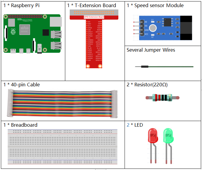
It’s definitely convenient to buy a whole kit, here’s the link:
Name |
ITEMS IN THIS KIT |
LINK |
|---|---|---|
Raphael Kit |
337 |
You can also buy them separately from the links below.
COMPONENT INTRODUCTION |
PURCHASE LINK |
|---|---|
- |
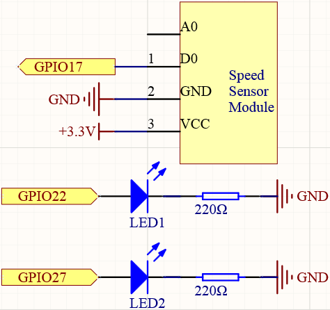
Schematic Diagram
Experimental Procedures
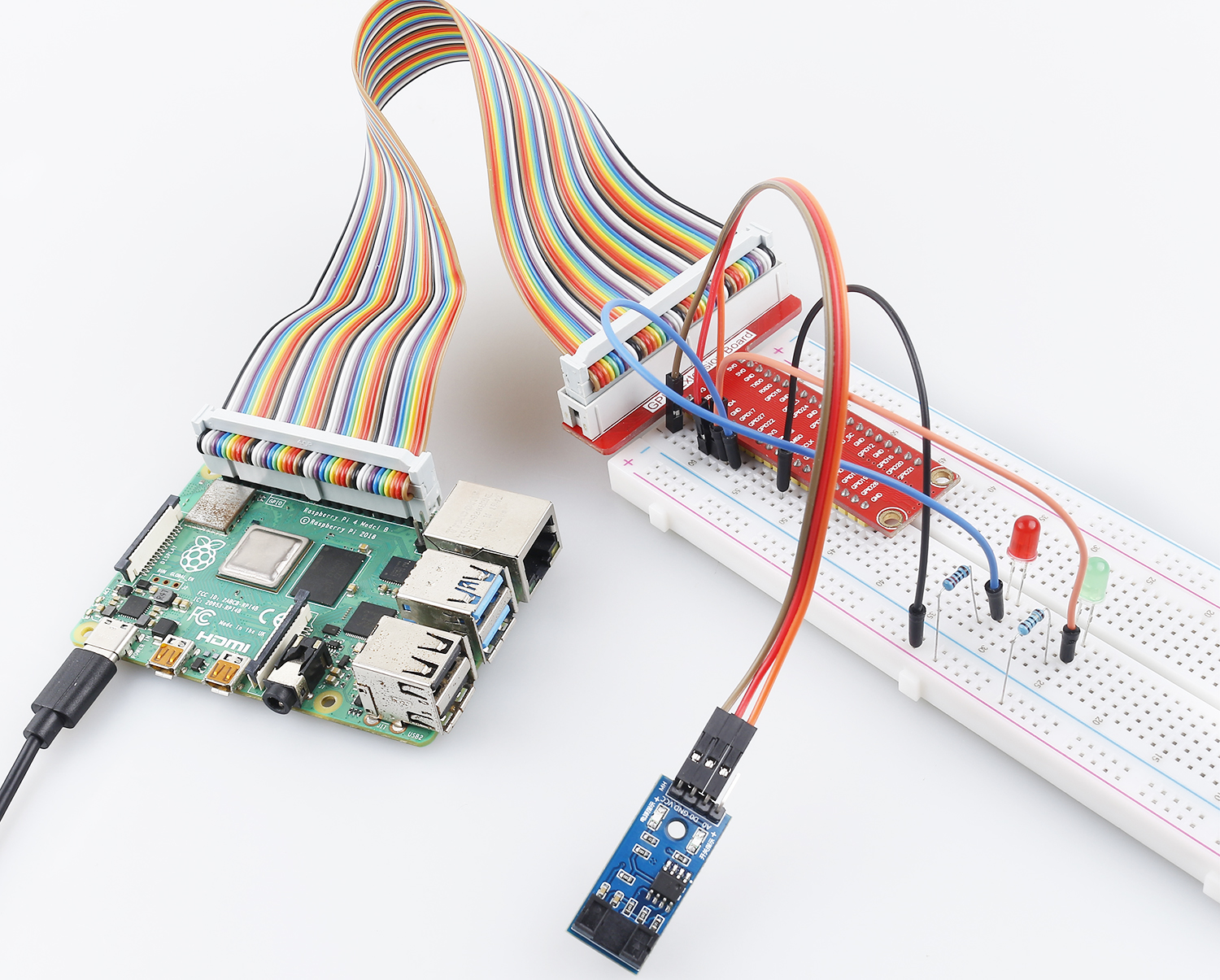
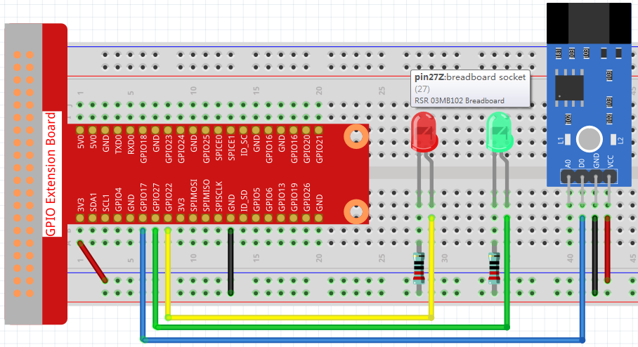
Step 1: Build the circuit.
Step 2: Change directory.
cd ~/raphael-kit/c/2.2.6/
Step 3: Compile.
gcc 2.2.6_speed_sensor_module.c -lwiringPi
Step 4: Run.
sudo ./a.out
After the code runs, the green LED will light up. If you place an obstacle in the gap of the speed sensor module, the “light blocked” will be printed on the screen and the red LED will be lit. Remove the obstacle and the green LED will light up again.
Note
If it does not work after running, or there is an error prompt: "wiringPi.h: No such file or directory", please refer to Install and Check the WiringPi.
Code
#include <wiringPi.h>
#include <stdio.h>

#define speedPin            0
#define Gpin                2
#define Rpin                3

void LED(int color)
{
    pinMode(Gpin, OUTPUT);
    pinMode(Rpin, OUTPUT);
    if (color == 0){
        digitalWrite(Rpin, HIGH);
        digitalWrite(Gpin, LOW);
    }
    else if (color == 1){
        digitalWrite(Rpin, LOW);
        digitalWrite(Gpin, HIGH);
    }
}

void Print(int x){
    if ( x == 0 ){
        printf("Light was blocked\n");
    }
}

int main(void){

    if(wiringPiSetup() == -1){ //when initialize wiring failed,print messageto screen
        printf("setup wiringPi failed !");
        return 1;
    }

    pinMode(speedPin, INPUT);
    int temp;
    while(1){
        //Reverse the input of speedPin
        if ( digitalRead(speedPin) == 0 ){
            temp = 1;
        }
        if ( digitalRead(speedPin) == 1 ){
            temp = 0;
        }

        LED(temp);
        Print(temp);
    }
    return 0;
}
Code Explanation
void LED(int color)
{
    pinMode(Gpin, OUTPUT);
    pinMode(Rpin, OUTPUT);
    if (color == 0){
        digitalWrite(Rpin, HIGH);
        digitalWrite(Gpin, LOW);
    }
    else if (color == 1){
        digitalWrite(Rpin, LOW);
        digitalWrite(Gpin, HIGH);
    }
}
Set a LED() function to control the 2 LEDs, the parameter of this function is color.
When color is 0, set Rpin to HIGH (light up the red LED) and Gpin to LOW (turn off the green LED); when color is 1, then light up the green LED and turn off the red LED.
while(1){
    //Reverse the input of speedPin
    if ( digitalRead(speedPin) == 0 ){
        temp = 1;
    }
    if ( digitalRead(speedPin) == 1 ){
        temp = 0;
    }

    LED(temp);
    Print(temp);
}
When you place an obstacle in the gap of the speed sensor module, speedPin is low level (0), then call LED(1) function to light up the green LED and “Light was blocked!” is printed.
Phenomenon Picture