Note
Hello, welcome to the SunFounder Raspberry Pi & Arduino & ESP32 Enthusiasts Community on Facebook! Dive deeper into Raspberry Pi, Arduino, and ESP32 with fellow enthusiasts.
Why Join?
Expert Support: Solve post-sale issues and technical challenges with help from our community and team.
Learn & Share: Exchange tips and tutorials to enhance your skills.
Exclusive Previews: Get early access to new product announcements and sneak peeks.
Special Discounts: Enjoy exclusive discounts on our newest products.
Festive Promotions and Giveaways: Take part in giveaways and holiday promotions.
👉 Ready to explore and create with us? Click [here] and join today!
2.2.1 Photoresistor
Note

Depending on your kit version, please identify whether you have ADC0834 or MCP3008 and proceed with the matching section.
Introduction
Photoresistor is a commonly used component of ambient light intensity in life. It helps the controller to recognize day and night and realize light control functions such as night lamp. This project is very similar to potentiometer, and you might think it changing the voltage to sensing light.
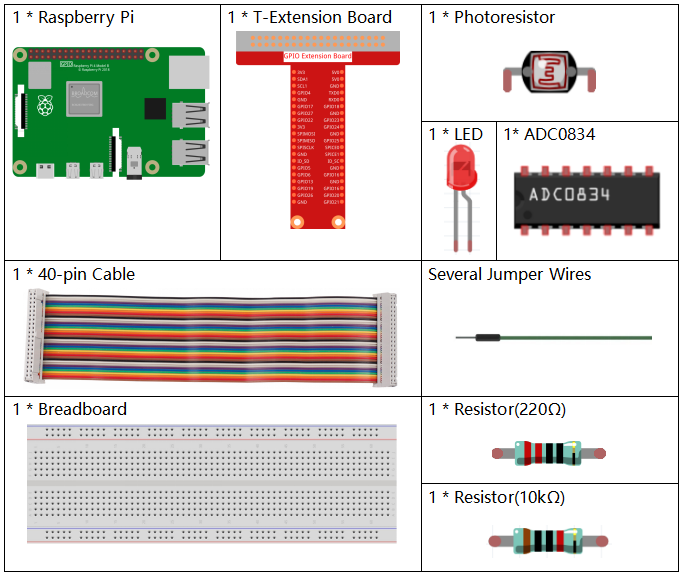
Required Components
In this project, we need the following components.
It’s definitely convenient to buy a whole kit, here’s the link:
Name |
ITEMS IN THIS KIT |
LINK |
|---|---|---|
Raphael Kit |
337 |
You can also buy them separately from the links below.
COMPONENT INTRODUCTION |
PURCHASE LINK |
|---|---|
- |
|
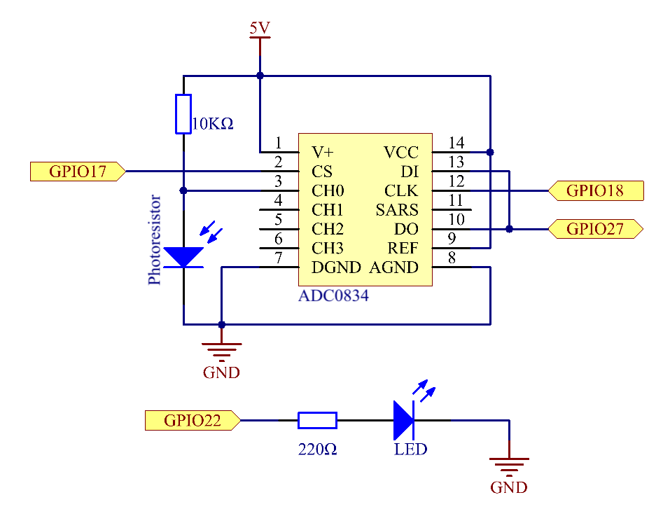
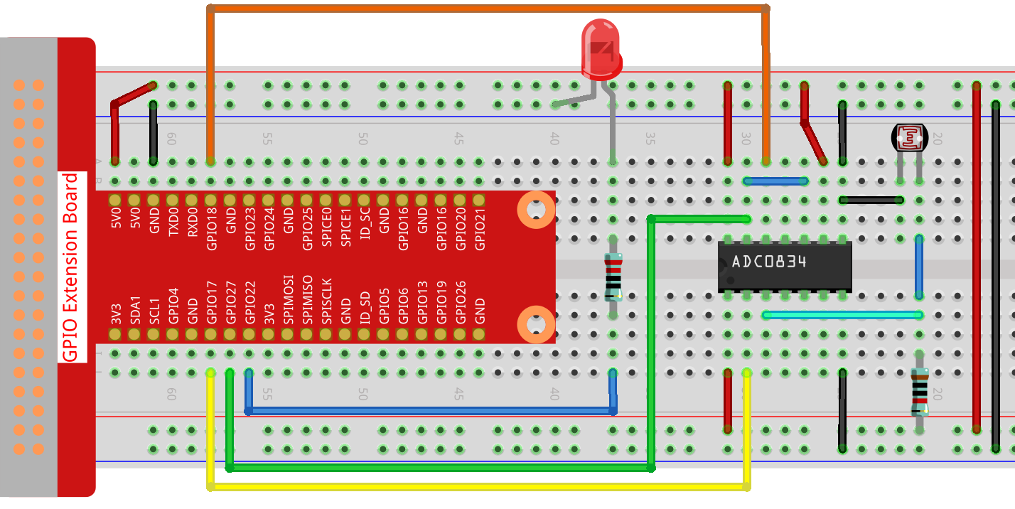
Schematic Diagram
Experimental Procedures
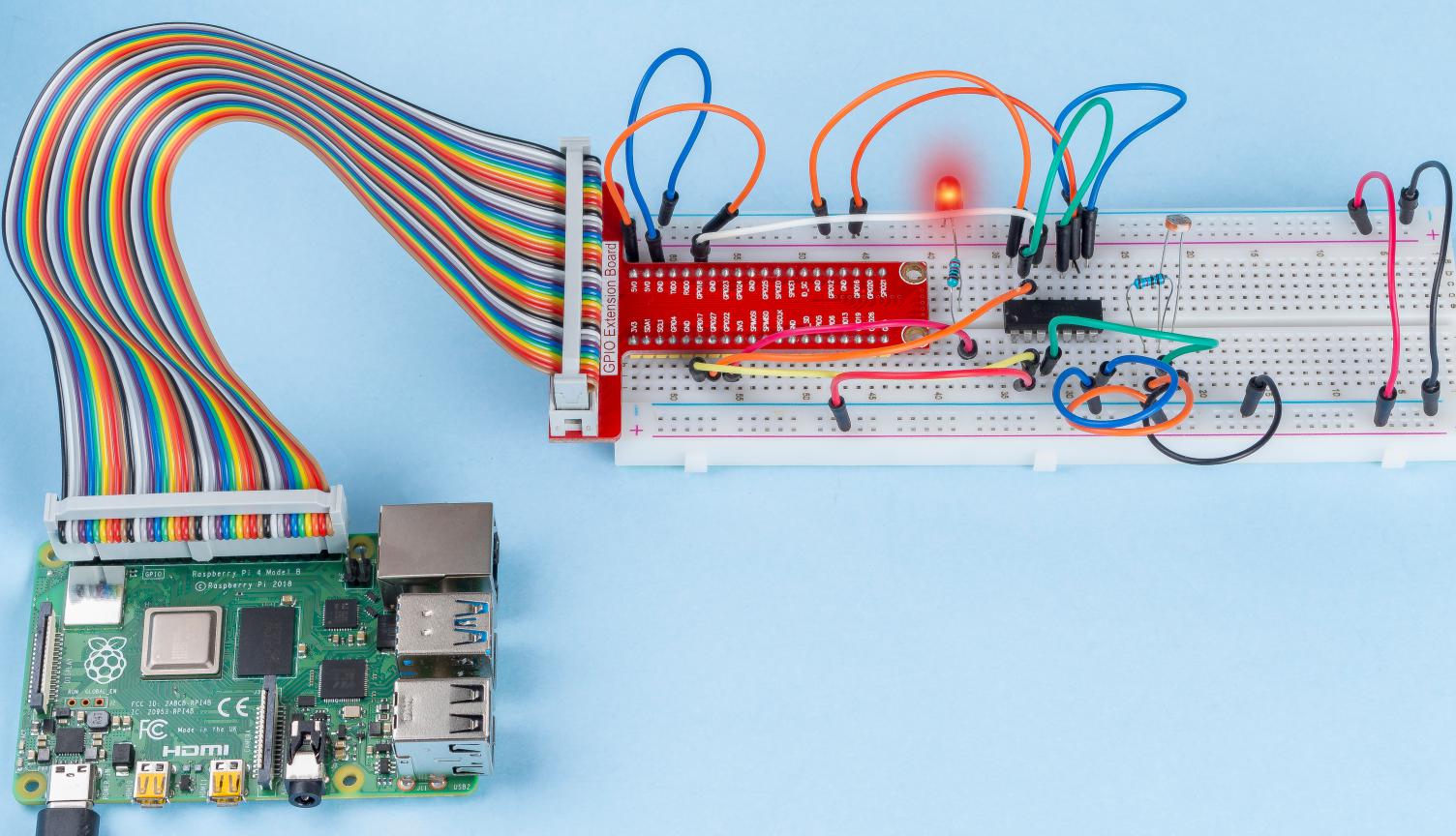
Step 1: Build the circuit.
Step 2: Go to the folder of the code.
cd ~/raphael-kit/c/2.2.1/
Step 3: Compile the code.
gcc 2.2.1_Photoresistor.c -lwiringPi
Step 4: Run the executable file.
sudo ./a.out
When the code is running, the brightness of the LED will change according to the light intensity sensed by the photoresistor.
Note
If it does not work after running, or there is an error prompt: "wiringPi.h: No such file or directory", please refer to Install and Check the WiringPi.
Code
#include <wiringPi.h>
#include <stdio.h>
#include <softPwm.h>

typedef unsigned char uchar;
typedef unsigned int uint;

#define     ADC_CS    0
#define     ADC_CLK   1
#define     ADC_DIO   2
#define     LedPin    3

uchar get_ADC_Result(uint channel)
{
    uchar i;
    uchar dat1=0, dat2=0;
    int sel = channel > 1 & 1;
    int odd = channel & 1;

    digitalWrite(ADC_CLK, 1);
    delayMicroseconds(2);
    digitalWrite(ADC_CLK, 0);
    delayMicroseconds(2);

    pinMode(ADC_DIO, OUTPUT);
    digitalWrite(ADC_CS, 0);
    // Start bit
    digitalWrite(ADC_CLK,0);
    digitalWrite(ADC_DIO,1);    delayMicroseconds(2);
    digitalWrite(ADC_CLK,1);    delayMicroseconds(2);
    //Single End mode
    digitalWrite(ADC_CLK,0);
    digitalWrite(ADC_DIO,1);    delayMicroseconds(2);
    digitalWrite(ADC_CLK,1);    delayMicroseconds(2);
    // ODD
    digitalWrite(ADC_CLK,0);
    digitalWrite(ADC_DIO,odd);  delayMicroseconds(2);
    digitalWrite(ADC_CLK,1);    delayMicroseconds(2);
    //Select
    digitalWrite(ADC_CLK,0);
    digitalWrite(ADC_DIO,sel);    delayMicroseconds(2);
    digitalWrite(ADC_CLK,1);

    digitalWrite(ADC_DIO,1);    delayMicroseconds(2);
    digitalWrite(ADC_CLK,0);
    digitalWrite(ADC_DIO,1);    delayMicroseconds(2);

    for(i=0;i<8;i++)
    {
        digitalWrite(ADC_CLK,1);    delayMicroseconds(2);
        digitalWrite(ADC_CLK,0);    delayMicroseconds(2);

        pinMode(ADC_DIO, INPUT);
        dat1=dat1<<1 | digitalRead(ADC_DIO);
    }

    for(i=0;i<8;i++)
    {
        dat2 = dat2 | ((uchar)(digitalRead(ADC_DIO))<<i);
        digitalWrite(ADC_CLK,1);    delayMicroseconds(2);
        digitalWrite(ADC_CLK,0);    delayMicroseconds(2);
    }

    digitalWrite(ADC_CS,1);
    pinMode(ADC_DIO, OUTPUT);
    return(dat1==dat2) ? dat1 : 0;
}

int main(void)
{
    uchar analogVal;
    if(wiringPiSetup() == -1){ //when initialize wiring failed,print messageto screen
        printf("setup wiringPi failed !");
        return 1;
    }
    softPwmCreate(LedPin,  0, 100);
    pinMode(ADC_CS,  OUTPUT);
    pinMode(ADC_CLK, OUTPUT);

    while(1){
        analogVal = get_ADC_Result(0);
        printf("Current analogVal : %d\n", analogVal);
        softPwmWrite(LedPin, analogVal);
        delay(100);
    }
    return 0;
}
Code Explanation
The codes here are the same as that in 2.1.4 Potentiometer. If you have any other questions, please check the code explanation of 2.1.7 Potentiometer for details.
Phenomenon Picture