Note
Hello, welcome to the SunFounder Raspberry Pi & Arduino & ESP32 Enthusiasts Community on Facebook! Dive deeper into Raspberry Pi, Arduino, and ESP32 with fellow enthusiasts.
Why Join?
Expert Support: Solve post-sale issues and technical challenges with help from our community and team.
Learn & Share: Exchange tips and tutorials to enhance your skills.
Exclusive Previews: Get early access to new product announcements and sneak peeks.
Special Discounts: Enjoy exclusive discounts on our newest products.
Festive Promotions and Giveaways: Take part in giveaways and holiday promotions.
👉 Ready to explore and create with us? Click [here] and join today!
2.1.3 Touch Switch Module
Introduction
In this project, you will learn about touch switch module. It can replace the traditional kinds of switch with these advantages: convenient operation, fine touch sense, precise control and least mechanical wear.
Required Components
In this project, we need the following components.
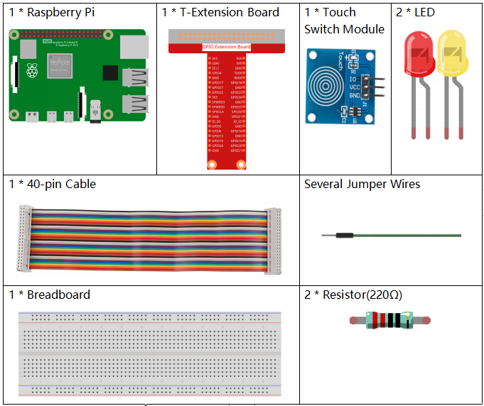
It’s definitely convenient to buy a whole kit, here’s the link:
Name |
ITEMS IN THIS KIT |
LINK |
|---|---|---|
Raphael Kit |
337 |
You can also buy them separately from the links below.
COMPONENT INTRODUCTION |
PURCHASE LINK |
|---|---|
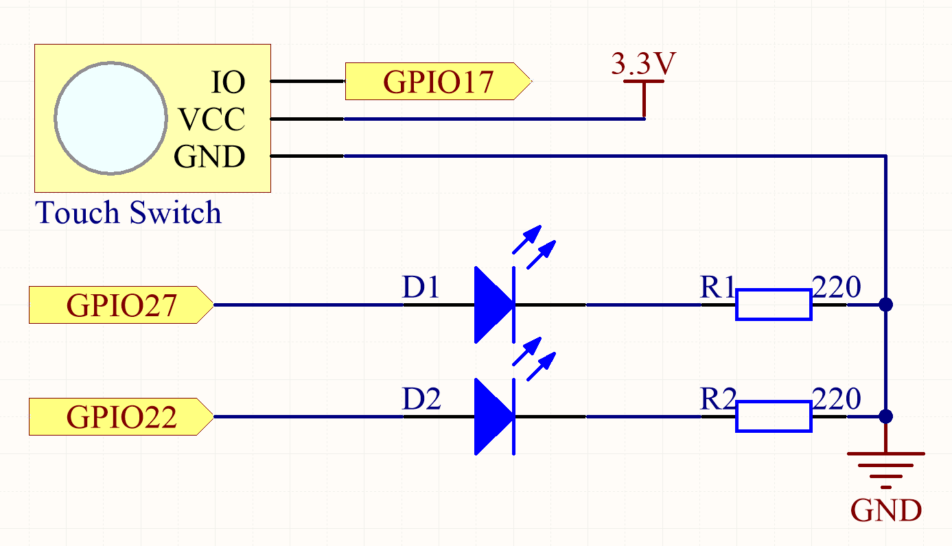
Schematic Diagram
Experimental Procedures
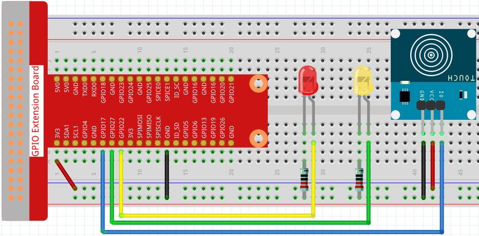
Step 1: Build the circuit.
Step 2: Change directory.
cd ~/raphael-kit/c/2.1.3/
Step 3: Compile.
gcc 2.1.3_TouchSwitch.c -lwiringPi
Step 4: Run.
sudo ./a.out
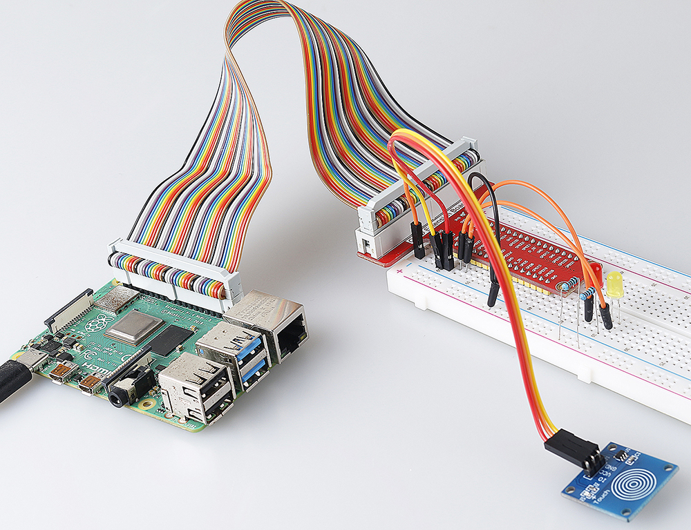
While the code is running, the red LED lights up; when you tap on the touch switch module, the yellow LED turns on.
Note
If it does not work after running, or there is an error prompt: "wiringPi.h: No such file or directory", please refer to Install and Check the WiringPi.
Code
#include <wiringPi.h>
#include <stdio.h>

#define touchPin               0
#define led1                   3
#define led2                   2

int main(void)
{
    // When initialize wiring failed, print message to screen
    if(wiringPiSetup() == -1){
        printf(etup w"siringPi failed !");
        return 1;
    }

    pinMode(touchPin, INPUT);
    pinMode(led1, OUTPUT);
    pinMode(led2, OUTPUT);

    while(1){
        // touch switch high, led1 on
        if(digitalRead(touchPin) == 1){
            digitalWrite(led1, LOW);
            digitalWrite(led2, HIGH);
            printf("You touch it! \r\n");
        }
        // touch switch low, led2 on
        if(digitalRead(touchPin) == 0){
            digitalWrite(led2, LOW);
            digitalWrite(led1, HIGH);
        }
    }

    return 0;
}
Code Explanation
#define touchPin               0
#define led1                   3
#define led2                   2
Pin GPIO17, GPIO22 and GPIO27 of the T_Extension Board is corresponding to
the GPIO0, GPIO3 and GPIO2 in wiringPi. Assign GPIO0, GPIO3 and GPIO2 to
touchPin, led1 and led2.
pinMode(touchPin, INPUT);
pinMode(led1, OUTPUT);
pinMode(led2, OUTPUT);
Set led1, led2 as output to write value to them and set touchPin as input to
read value from it.
while(1){
    // touch switch high, led1 on
        if(digitalRead(touchPin) == 1){
        digitalWrite(led1, LOW);
        digitalWrite(led2, HIGH);
        printf("You touch it! \r\n");
    }
    // touch switch low, led2 on
    if(digitalRead(touchPin) == 0){
        digitalWrite(led2, LOW);
        digitalWrite(led1, HIGH);
    }
}
Set an infinite loop, when you tap on the touch switch module, touchPin is high, led1 will light up and print “You touch it!” . When touchPin is low, led2 will light up.
Phenomenon Picture