Note
Hello, welcome to the SunFounder Raspberry Pi & Arduino & ESP32 Enthusiasts Community on Facebook! Dive deeper into Raspberry Pi, Arduino, and ESP32 with fellow enthusiasts.
Why Join?
Expert Support: Solve post-sale issues and technical challenges with help from our community and team.
Learn & Share: Exchange tips and tutorials to enhance your skills.
Exclusive Previews: Get early access to new product announcements and sneak peeks.
Special Discounts: Enjoy exclusive discounts on our newest products.
Festive Promotions and Giveaways: Take part in giveaways and holiday promotions.
👉 Ready to explore and create with us? Click [here] and join today!
2.1.1 Button
Introduction
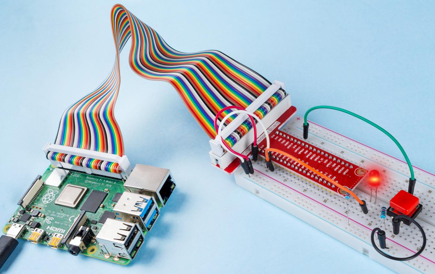
In this project, we will learn how to turn on or off the LED by using a button.
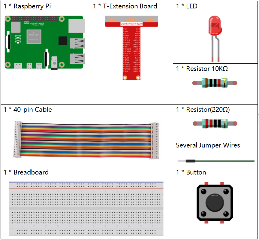
Required Components
In this project, we need the following components.
It’s definitely convenient to buy a whole kit, here’s the link:
Name |
ITEMS IN THIS KIT |
LINK |
|---|---|---|
Raphael Kit |
337 |
You can also buy them separately from the links below.
COMPONENT INTRODUCTION |
PURCHASE LINK |
|---|---|
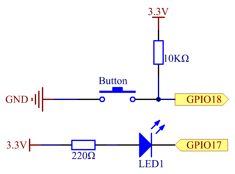
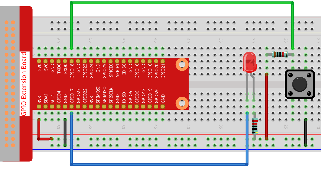
Schematic Diagram
Use a normally open button as the input of Raspberry Pi, the connection is shown in the schematic diagram below. When the button is pressed, the GPIO18 will turn into low level (0V). We can detect the state of the GPIO18 through programming. That is, if the GPIO18 turns into low level, it means the button is pressed. You can run the corresponding code when the button is pressed, and then the LED will light up.
Note
The longer pin of the LED is the anode and the shorter one is the cathode.
Experimental Procedures
Step 1: Build the circuit.
Step 2: Open the code file.
cd ~/raphael-kit/c/2.1.1/
Note
Change directory to the path of the code in this experiment via cd.
Step 3: Compile the code.
gcc 2.1.1_Button.c -lwiringPi
Step 4: Run the executable file.
sudo ./a.out
After the code runs, press the button, the LED lights up; otherwise, turns off.
Note
If it does not work after running, or there is an error prompt: "wiringPi.h: No such file or directory", please refer to Install and Check the WiringPi.
Code
#include <wiringPi.h>
#include <stdio.h>

#define LedPin      0
#define ButtonPin   1

int main(void){
    // When initialize wiring failed, print message to screen
    if(wiringPiSetup() == -1){
        printf("setup wiringPi failed !");
        return 1;
    }

    pinMode(LedPin, OUTPUT);
    pinMode(ButtonPin, INPUT);
    digitalWrite(LedPin, HIGH);

    while(1){
        // Indicate that button has pressed down
        if(digitalRead(ButtonPin) == 0){
            // Led on
            digitalWrite(LedPin, LOW);
        //  printf("...LED on\n");
        }
        else{
            // Led off
            digitalWrite(LedPin, HIGH);
        //  printf("LED off...\n");
        }
    }
    return 0;
}
Code Explanation
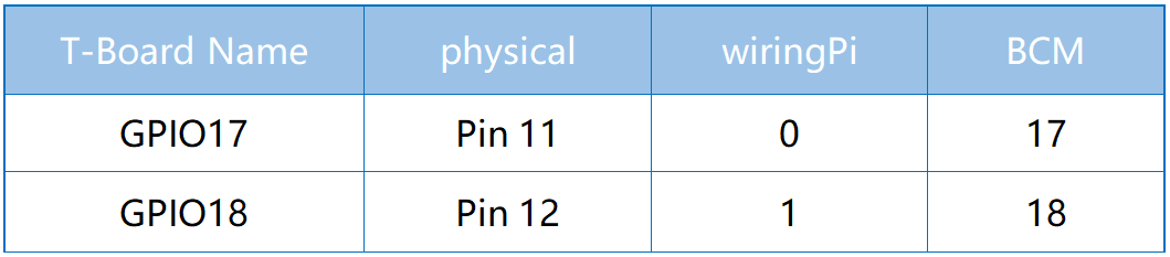
#define LedPin 0
Pin GPIO17 in the T_Extension Board is equal to the GPIO0 in the wiringPi.
#define ButtonPin 1
ButtonPin is connected to GPIO1.
pinMode(LedPin, OUTPUT);
Set LedPin as output to assign value to it.
pinMode(ButtonPin, INPUT);
Set ButtonPin as input to read the value of ButtonPin.
while(1){
        // Indicate that button has pressed down
        if(digitalRead(ButtonPin) == 0){
            // Led on
            digitalWrite(LedPin, LOW);
        //  printf("...LED on\n");
        }
        else{
            // Led off
            digitalWrite(LedPin, HIGH);
        //  printf("LED off...\n");
        }
    }
if (digitalRead (ButtonPin) == 0) : check whether the button has been
pressed. Execute digitalWrite(LedPin, LOW) when button is pressed to
light up LED.
digitalRead() function is to read HIGH (high level) or LOW (low level) of
the input parameter word pin, it returns 1 when pin is HIGH and returns 0
when pin is LOW.
digitalWrite() function is to write HIGH (high level) or LOW (low level) to
the input parameter word pin.
Phenomenon Picture