Note
Hello, welcome to the SunFounder Raspberry Pi & Arduino & ESP32 Enthusiasts Community on Facebook! Dive deeper into Raspberry Pi, Arduino, and ESP32 with fellow enthusiasts.
Why Join?
Expert Support: Solve post-sale issues and technical challenges with help from our community and team.
Learn & Share: Exchange tips and tutorials to enhance your skills.
Exclusive Previews: Get early access to new product announcements and sneak peeks.
Special Discounts: Enjoy exclusive discounts on our newest products.
Festive Promotions and Giveaways: Take part in giveaways and holiday promotions.
👉 Ready to explore and create with us? Click [here] and join today!
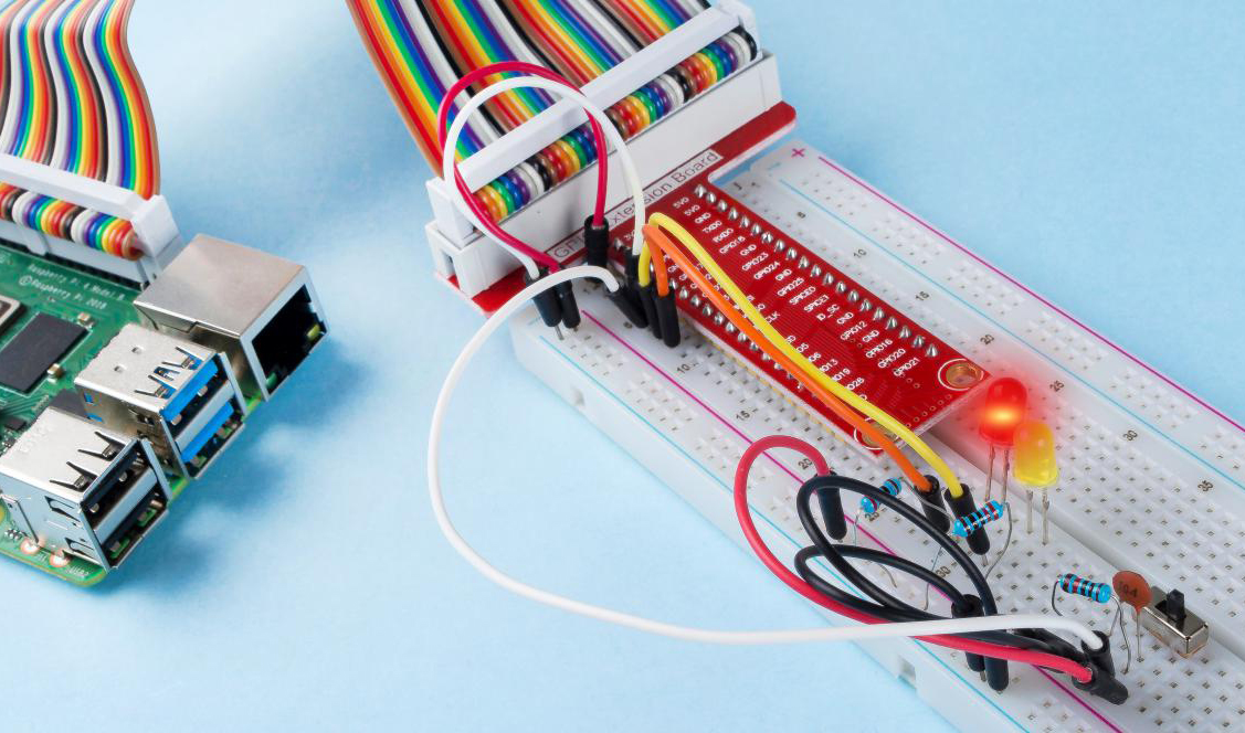
2.1.4 Slide Switch
Introduction
In this project, we will learn how to use a slide switch. Usually,the slide switch is soldered on PCB as a power switch, but here we need to insert it into the breadboard, thus it may not be tightened. And we use it on the breadboard to show its function.
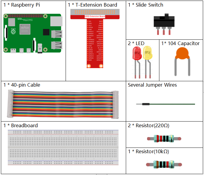
Required Components
In this project, we need the following components.
It’s definitely convenient to buy a whole kit, here’s the link:
Name |
ITEMS IN THIS KIT |
LINK |
|---|---|---|
Raphael Kit |
337 |
You can also buy them separately from the links below.
COMPONENT INTRODUCTION |
PURCHASE LINK |
|---|---|
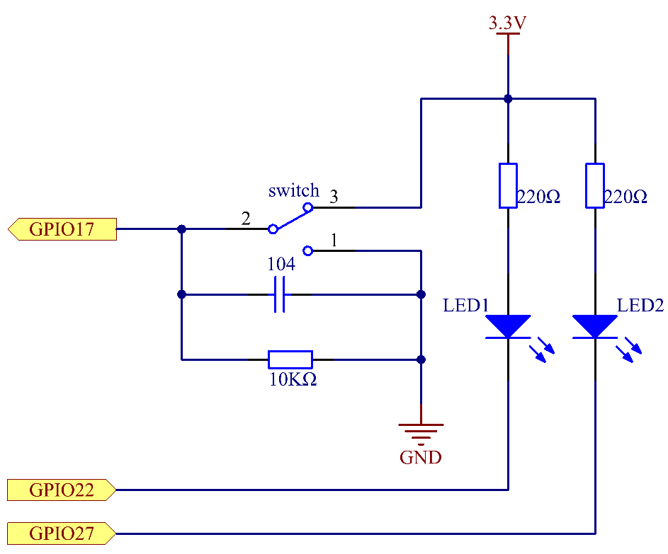
Schematic Diagram
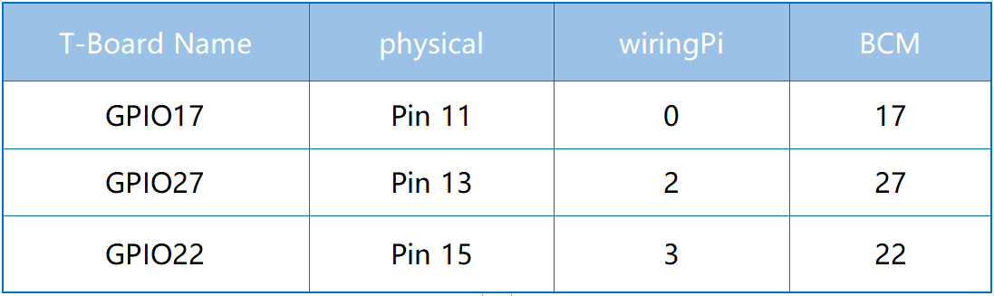
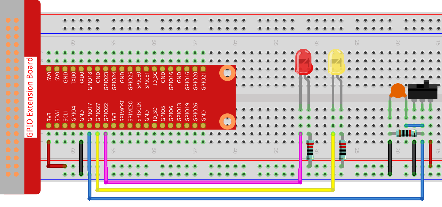
Connect the middle pin of the Slide Switch to GPIO17, and two LEDs to pin GPIO22 and GPIO27 respectively. Then when you pull the slide, you can see the two LEDs light up alternately.
Experimental Procedures
Step 1: Build the circuit.
Step 2: Go to the folder of the code.
cd ~/raphael-kit/c/2.1.4
Step 3: Compile.
gcc 2.1.4_Slider.c -lwiringPi
Step 4: Run the executable file above.
sudo ./a.out
While the code is running, get the switch connected to the left, then the yellow LED lights up; to the right, the red light turns on.
Note
If it does not work after running, or there is an error prompt: "wiringPi.h: No such file or directory", please refer to Install and Check the WiringPi.
Code
#include <wiringPi.h>
#include <stdio.h>
#define slidePin        0
#define led1            3
#define led2            2

int main(void)
{
    // When initialize wiring failed, print message to screen
    if(wiringPiSetup() == -1){
        printf("setup wiringPi failed !");
        return 1;
    }
    pinMode(slidePin, INPUT);
    pinMode(led1, OUTPUT);
    pinMode(led2, OUTPUT);
    while(1){
        // slide switch high, led1 on
        if(digitalRead(slidePin) == 1){
            digitalWrite(led1, LOW);
            digitalWrite(led2, HIGH);
            printf("LED1 on\n");
        }
        // slide switch low, led2 on
        if(digitalRead(slidePin) == 0){
            digitalWrite(led2, LOW);
            digitalWrite(led1, HIGH);
            printf(".....LED2 on\n");
        }
    }
    return 0;
}
Code Explanation
if(digitalRead(slidePin) == 1){
            digitalWrite(led1, LOW);
            digitalWrite(led2, HIGH);
            printf("LED1 on\n");
    }
When the slide is pulled to the right, the middle pin and right one are connected; the Raspberry Pi reads a high level at the middle pin, so the LED1 is on and LED2 off
if(digitalRead(slidePin) == 0){
            digitalWrite(led2, LOW);
            digitalWrite(led1, HIGH);
            printf(".....LED2 on\n");
        }
When the slide is pulled to the left, the middle pin and left one are connected; the Raspberry Pi reads a low, so the LED2 is on and LED1 off
Phenomenon Picture