Note
Hello, welcome to the SunFounder Raspberry Pi & Arduino & ESP32 Enthusiasts Community on Facebook! Dive deeper into Raspberry Pi, Arduino, and ESP32 with fellow enthusiasts.
Why Join?
Expert Support: Solve post-sale issues and technical challenges with help from our community and team.
Learn & Share: Exchange tips and tutorials to enhance your skills.
Exclusive Previews: Get early access to new product announcements and sneak peeks.
Special Discounts: Enjoy exclusive discounts on our newest products.
Festive Promotions and Giveaways: Take part in giveaways and holiday promotions.
👉 Ready to explore and create with us? Click [here] and join today!
2.1.9 Joystick
Note

Depending on your kit version, please identify whether you have ADC0834 or MCP3008 and proceed with the matching section.
Introduction
In this project, We’re going to learn how joystick works. We manipulate the Joystick and display the results on the screen.
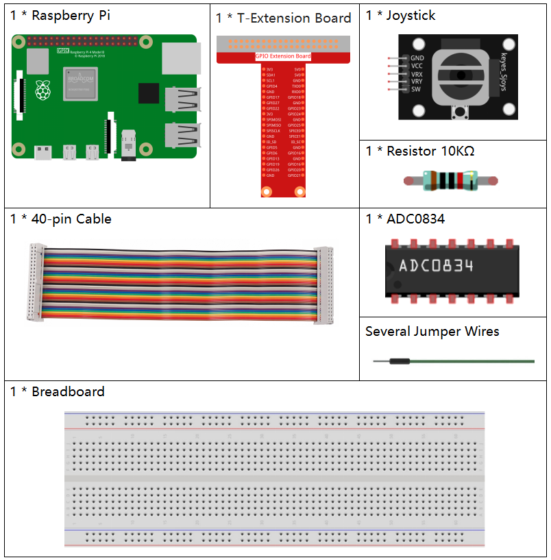
Required Components
In this project, we need the following components.
It’s definitely convenient to buy a whole kit, here’s the link:
Name |
ITEMS IN THIS KIT |
LINK |
|---|---|---|
Raphael Kit |
337 |
You can also buy them separately from the links below.
COMPONENT INTRODUCTION |
PURCHASE LINK |
|---|---|
- |
|
- |
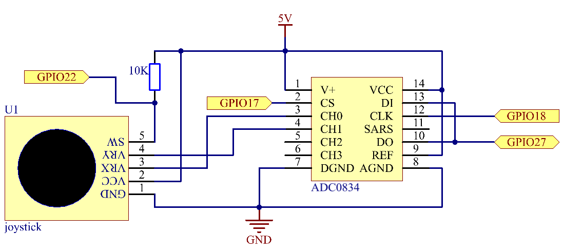
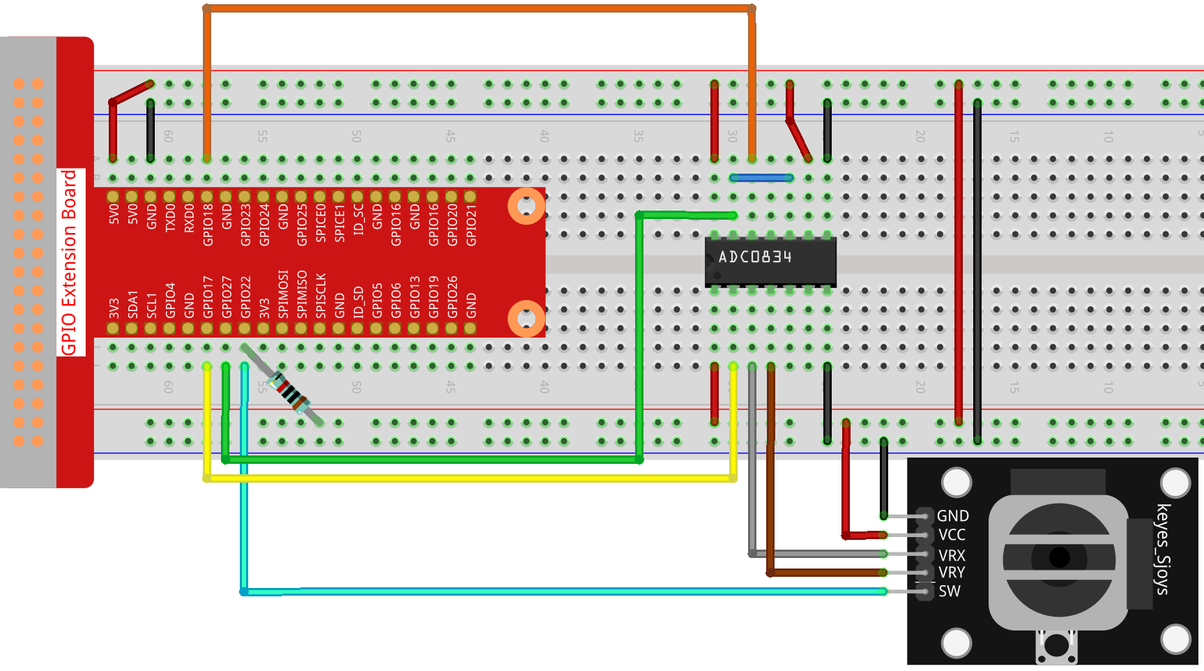
Schematic Diagram
When the data of joystick is read, there are some differents between axis: data of X and Y axis is analog, which need to use ADC0834 to convert the analog value to digital value. Data of Z axis is digital, so you can directly use the GPIO to read, or you can also use ADC to read.
Experimental Procedures
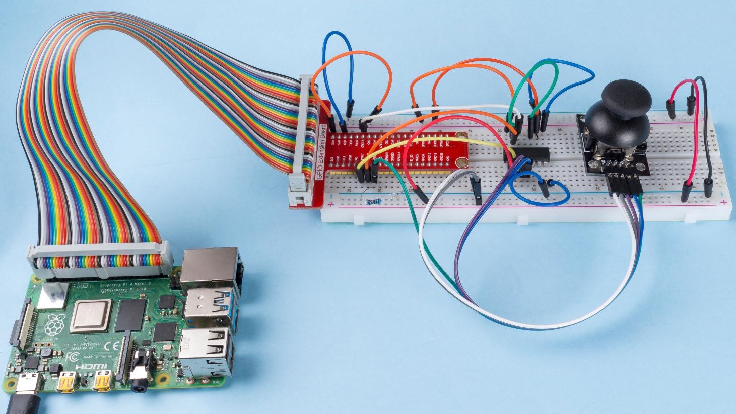
Step 1: Build the circuit.
Step 2: Go to the folder of the code.
cd ~/raphael-kit/c/2.1.9/
Step 3: Compile the code.
gcc 2.1.9_Joystick.c -lwiringPi
Step 4: Run the executable file.
sudo ./a.out
After the code runs, turn the Joystick, then the corresponding values of x, y, Btn are displayed on screen.
Note
If it does not work after running, or there is an error prompt: "wiringPi.h: No such file or directory", please refer to Install and Check the WiringPi.
Code
#include <wiringPi.h>
#include <stdio.h>
#include <softPwm.h>
typedef unsigned char uchar;
typedef unsigned int uint;
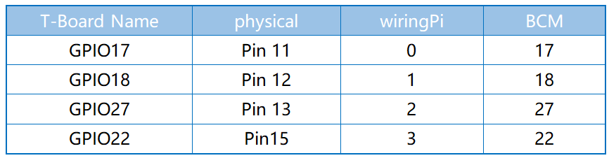
#define ADC_CS 0
#define ADC_CLK 1
#define ADC_DIO 2
#define BtnPin 3
uchar get_ADC_Result(uint channel)
{
uchar i;
uchar dat1=0, dat2=0;
int sel = channel > 1 & 1;
int odd = channel & 1;
digitalWrite(ADC_CLK, 1);
delayMicroseconds(2);
digitalWrite(ADC_CLK, 0);
delayMicroseconds(2);
pinMode(ADC_DIO, OUTPUT);
digitalWrite(ADC_CS, 0);
// Start bit
digitalWrite(ADC_CLK,0);
digitalWrite(ADC_DIO,1); delayMicroseconds(2);
digitalWrite(ADC_CLK,1); delayMicroseconds(2);
//Single End mode
digitalWrite(ADC_CLK,0);
digitalWrite(ADC_DIO,1); delayMicroseconds(2);
digitalWrite(ADC_CLK,1); delayMicroseconds(2);
// ODD
digitalWrite(ADC_CLK,0);
digitalWrite(ADC_DIO,odd); delayMicroseconds(2);
digitalWrite(ADC_CLK,1); delayMicroseconds(2);
//Select
digitalWrite(ADC_CLK,0);
digitalWrite(ADC_DIO,sel); delayMicroseconds(2);
digitalWrite(ADC_CLK,1);
digitalWrite(ADC_DIO,1); delayMicroseconds(2);
digitalWrite(ADC_CLK,0);
digitalWrite(ADC_DIO,1); delayMicroseconds(2);
for(i=0;i<8;i++)
{
digitalWrite(ADC_CLK,1); delayMicroseconds(2);
digitalWrite(ADC_CLK,0); delayMicroseconds(2);
pinMode(ADC_DIO, INPUT);
dat1=dat1<<1 | digitalRead(ADC_DIO);
}
for(i=0;i<8;i++)
{
dat2 = dat2 | ((uchar)(digitalRead(ADC_DIO))<<i);
digitalWrite(ADC_CLK,1); delayMicroseconds(2);
digitalWrite(ADC_CLK,0); delayMicroseconds(2);
}
digitalWrite(ADC_CS,1);
pinMode(ADC_DIO, OUTPUT);
return(dat1==dat2) ? dat1 : 0;
}
int main(void)
{
uchar x_val;
uchar y_val;
uchar btn_val;
if(wiringPiSetup() == -1){ //when initialize wiring failed,print messageto screen
printf("setup wiringPi failed !");
return 1;
}
pinMode(BtnPin, INPUT);
pullUpDnControl(BtnPin, PUD_UP);
pinMode(ADC_CS, OUTPUT);
pinMode(ADC_CLK, OUTPUT);
while(1){
x_val = get_ADC_Result(0);
y_val = get_ADC_Result(1);
btn_val = digitalRead(BtnPin);
printf("x = %d, y = %d, btn = %d\n", x_val, y_val, btn_val);
delay(100);
}
return 0;
}
Code Explanation
uchar get_ADC_Result(uint channel)
{
    uchar i;
    uchar dat1=0, dat2=0;
    int sel = channel > 1 & 1;
    int odd = channel & 1;
    pinMode(ADC_DIO, OUTPUT);
    digitalWrite(ADC_CS, 0);
    // Start bit
    digitalWrite(ADC_CLK,0);
    digitalWrite(ADC_DIO,1);    delayMicroseconds(2);
    digitalWrite(ADC_CLK,1);    delayMicroseconds(2);
    //Single End mode
    digitalWrite(ADC_CLK,0);
    digitalWrite(ADC_DIO,1);    delayMicroseconds(2);
    digitalWrite(ADC_CLK,1);    delayMicroseconds(2);
    ......
The working process of the function is detailed in 2.1.7 Potentiometer.
while(1){
        x_val = get_ADC_Result(0);
        y_val = get_ADC_Result(1);
        btn_val = digitalRead(BtnPin);
        printf("x = %d, y = %d, btn = %d\n", x_val, y_val, btn_val);
        delay(100);
    }
VRX and VRY of Joystick are connected to CH0, CH1 of ADC0834 respectively. So the function getResult() is called to read the values of CH0 and CH1. Then the read values should be stored in the variables x_val and y_val. In addition, read the value of SW of joystick and store it into the variable Btn_val. Finally, the values of x_val, y_val and Btn_val shall be printed with print() function.
Phenomenon Picture