MPU6050 Module
MPU6050

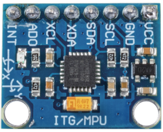
The MPU-6050 is a 6-axis(combines 3-axis Gyroscope, 3-axis Accelerometer) motion tracking devices.
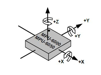
Its three coordinate systems are defined as follows:
Put MPU6050 flat on the table, assure that the face with label is upward and a dot on this surface is on the top left corner. Then the upright direction upward is the z-axis of the chip. The direction from left to right is regarded as the X-axis. Accordingly the direction from back to front is defined as the Y-axis.

3-axis Accelerometer
The accelerometer works on the principle of piezo electric effect, the ability of certain materials to generate an electric charge in response to applied mechanical stress.
Here, imagine a cuboidal box, having a small ball inside it, like in the picture above. The walls of this box are made with piezo electric crystals. Whenever you tilt the box, the ball is forced to move in the direction of the inclination, due to gravity. The wall with which the ball collides, creates tiny piezo electric currents. There are totally, three pairs of opposite walls in a cuboid. Each pair corresponds to an axis in 3D space: X, Y and Z axes. Depending on the current produced from the piezo electric walls, we can determine the direction of inclination and its magnitude.

We can use the MPU6050 to detect its acceleration on each coordinate axis (in the stationary desktop state, the Z-axis acceleration is 1 gravity unit, and the X and Y axes are 0). If it is tilted or in a weightless/overweight condition, the corresponding reading will change.
There are four kinds of measuring ranges that can be selected programmatically: +/-2g, +/-4g, +/-8g, and +/-16g (2g by default) corresponding to each precision. Values range from -32768 to 32767.
The reading of accelerometer is converted to an acceleration value by mapping the reading from the reading range to the measuring range.
Acceleration = (Accelerometer axis raw data / 65536 * full scale Acceleration range) g
Take the X-axis as an example, when Accelerometer X axis raw data is 16384 and the range is selected as +/-2g:
Acceleration along the X axis = (16384 / 65536 * 4) g =1g
3-axis Gyroscope
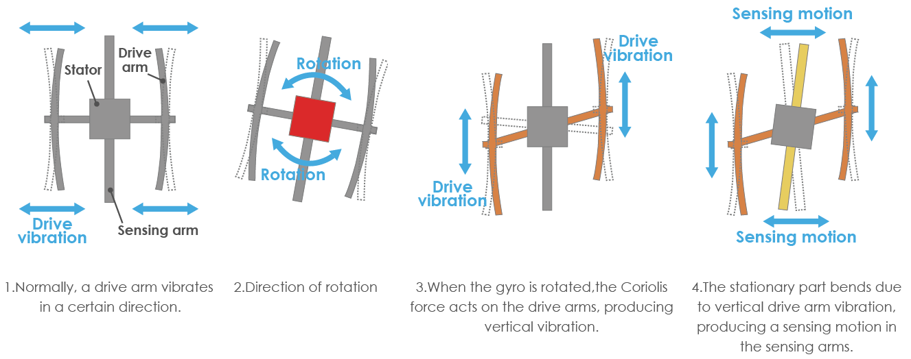
Gyroscopes work on the principle of Coriolis acceleration. Imagine that there is a fork like structure, that is in constant back and forth motion. It is held in place using piezo electric crystals. Whenever, you try to tilt this arrangement, the crystals experience a force in the direction of inclination. This is caused as a result of the inertia of the moving fork. The crystals thus produce a current in consensus with the piezo electric effect, and this current is amplified.

The Gyroscope also has four kinds of measuring ranges: +/- 250, +/- 500, +/- 1000, +/- 2000. The calculation method and Acceleration are basically consistent.
The formula for converting the reading into angular velocity is as follows:
Angular velocity = (Gyroscope axis raw data / 65536 * full scale Gyroscope range) °/s
The X axis, for example, the Accelerometer X axis raw data is 16384 and ranges + / - 250°/ s:
Angular velocity along the X axis = (16384 / 65536 * 500)°/s =125°/s
Example
6.3 6-axis Motion Tracking (For MicroPython User)
7.11 Somatosensory Controller (For MicroPython User)
7.12 Digital Bubble Level (For MicroPython User)
6.3 - 6-axis Motion Tracking (For Arduino User)