注釈
こんにちは、SunFounder Raspberry Pi & Arduino & ESP32 愛好家コミュニティ(Facebook)へようこそ! Raspberry Pi、Arduino、ESP32 を仲間と一緒にさらに深く探求しましょう。
参加する理由
専門的サポート: 購入後の問題や技術的課題を、コミュニティとチームがサポートします。
学びと共有: ヒントやチュートリアルを交換してスキルを向上できます。
限定プレビュー: 新製品の発表やプレビューに早くアクセスできます。
特別割引: 最新製品を会員限定の割引価格で購入できます。
季節イベントと景品企画: プレゼントや季節ごとのイベントに参加できます。
👉 一緒に探求と創造を始めましょう。[ここ] をクリックして今すぐ参加!
3.1.8 過熱モニター(MCP3008)
注釈
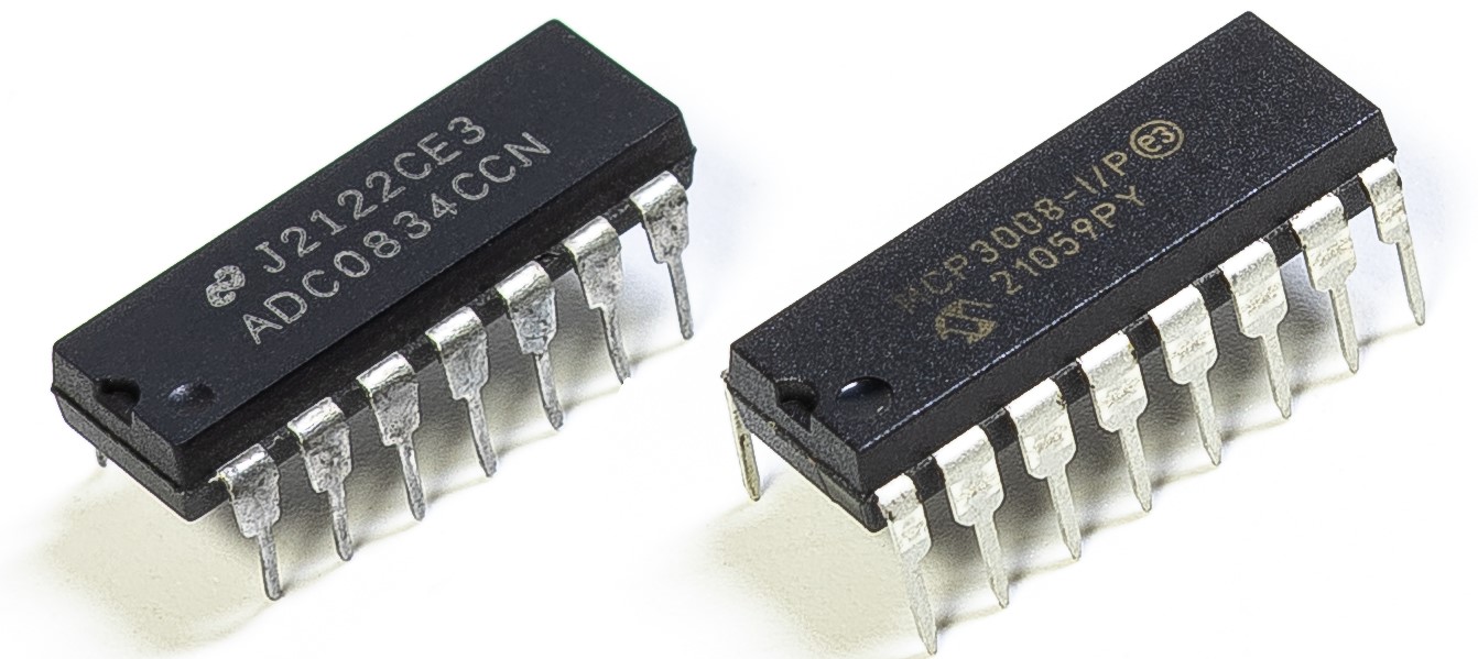
キットのバージョンによって ADC0834 または MCP3008 が含まれています。 該当する方のセクションを進めてください。
はじめに
工場などの環境で回路が過熱した際に、アラームを鳴らし、機械を即座に自動停止させるような 過熱監視装置を作りたい場合があります。 本プロジェクトでは、サーミスタ、ジョイスティック、ブザー、LED、LCD を用いて、 閾値を調整可能なスマート温度監視装置を製作します。
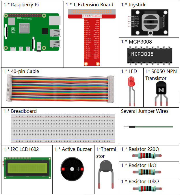
必要な部品
このプロジェクトで使用する部品は以下の通りです。
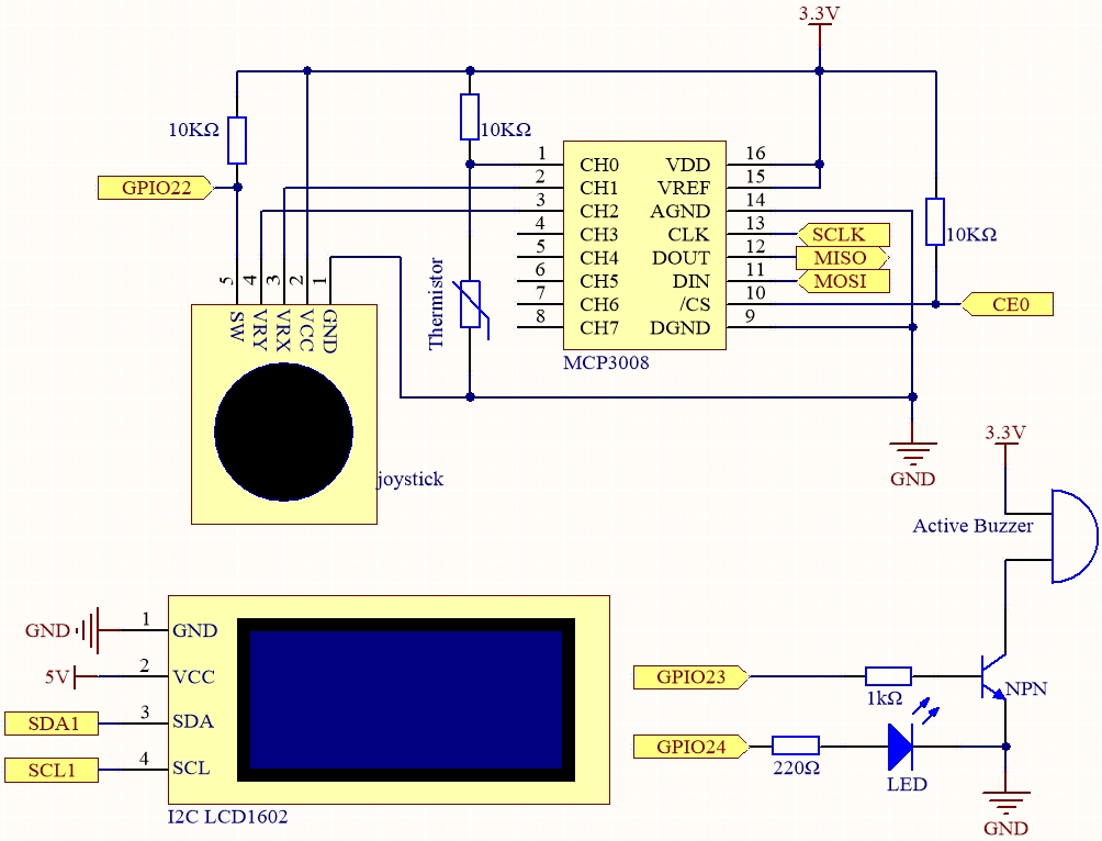
回路図
T-Board 名 |
物理ピン |
wiringPi |
BCM |
SPICE0 |
Pin 24 |
10 |
8 |
SPIMOSI |
Pin 19 |
12 |
10 |
SPIMISO |
Pin 21 |
13 |
9 |
SPISCLK |
Pin 23 |
14 |
11 |
GPIO22 |
Pin15 |
3 |
22 |
GPIO23 |
Pin16 |
4 |
23 |
GPIO24 |
Pin18 |
5 |
24 |
SDA1 |
Pin 3 |
||
SCL1 |
Pin 5 |
実験手順
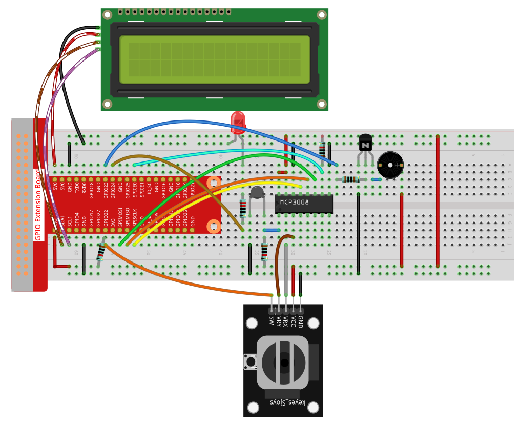
手順1: 回路を組み立てます。
手順2: SPI インターフェースを設定し、 spidev ライブラリをインストールします(詳細は SPI 設定 を参照)。すでに設定済みであれば省略できます。
手順3: コードのフォルダに移動します。
cd ~/davinci-kit-for-raspberry-pi/python-pi5
手順4: 実行ファイルを起動します。
sudo python3 3.1.8-2_OverheatMonitor_zero.py
プログラム実行中は、現在の温度と高温閾値 40 が I2C LCD1602 に表示されます。 現在の温度が閾値を超えると、ブザーと LED が作動し警告します。
ジョイスティック を押すことで、高温閾値の調整モードに切り替えます。 X軸・Y軸方向にジョイスティックを倒すと、閾値を上げ下げできます。 ジョイスティックを再度押すと閾値が初期値にリセットされます。
注釈
FileNotFoundError: [Errno 2] No such file or directory: '/dev/i2c-1'が表示された場合は、I²C 設定 を参照して I2C を有効にしてください。ModuleNotFoundError: No module named 'smbus2'エラーが出た場合はsudo pip3 install smbus2を実行してください。OSError: [Errno 121] Remote I/O errorが表示される場合は、モジュールの配線ミスまたは故障が原因です。配線とコードに問題がなくても LCD に表示されない場合は、背面の可変抵抗を回してコントラストを調整してください。
警告
RuntimeError: Cannot determine SOC peripheral base address というエラーが出た場合は、「gpiozero」が動作しない場合。 を参照してください。
コード
#!/usr/bin/env python3

import LCD1602
from gpiozero import LED, Buzzer, Button
import spidev
import time
import math

# ジョイスティックボタン、ブザー、LED の初期化
Joy_BtnPin = Button(22)  # GPIO22, Pin15
buzzPin = Buzzer(23)     # GPIO23, Pin16
ledPin = LED(24)         # GPIO24, Pin18

# 高温閾値の初期設定
upperTem = 40

# MCP3008 用 SPI 初期化(バス0, CE0 -> GPIO8 / Pin24)
spi = spidev.SpiDev()
spi.open(0, 0)
spi.max_speed_hz = 1000000  # 1 MHz

# LCD 初期化(I2C アドレス 0x27, バックライト ON)
LCD1602.init(0x27, 1)

def read_adc(channel):
    """
    MCP3008(0〜7チャンネル)のアナログ値を読み取る
    """
    if channel < 0 or channel > 7:
        return -1
    adc = spi.xfer2([1, (8 + channel) << 4, 0])
    value = ((adc[1] & 0x03) << 8) | adc[2]
    return value

def get_joystick_value():
    """
    ジョイスティックの値を読み取り、位置に応じた変化量を返す
    """
    x_val = read_adc(1)
    y_val = read_adc(2)
    if x_val > 800:
        return 1
    elif x_val < 200:
        return -1
    elif y_val > 800:
        return -10
    elif y_val < 200:
        return 10
    else:
        return 0

def upper_tem_setting():
    """
    高温閾値を調整し、LCD に表示
    """
    global upperTem
    LCD1602.write(0, 0, 'Upper Adjust: ')
    change = int(get_joystick_value())
    upperTem += change
    strUpperTem = str(upperTem)
    LCD1602.write(0, 1, strUpperTem)
    LCD1602.write(len(strUpperTem), 1, '              ')
    time.sleep(0.1)

def temperature():
    """
    センサーから現在の温度を取得(摂氏)して返す
    """
    analogVal = read_adc(0)
    Vr = 3.3 * analogVal / 1023.0
    if Vr == 0:
        return 0
    Rt = 10000.0 * Vr / (3.3 - Vr)
    temp = 1 / (((math.log(Rt / 10000.0)) / 3950.0) + (1 / (273.15 + 25.0)))
    Cel = temp - 273.15
    return round(Cel, 2)

def monitoring_temp():
    """
    現在温度と閾値を表示し、閾値超過時にブザーとLEDを作動
    """
    global upperTem
    Cel = temperature()
    LCD1602.write(0, 0, 'Temp: ')
    LCD1602.write(0, 1, 'Upper: ')
    LCD1602.write(6, 0, str(Cel))
    LCD1602.write(7, 1, str(upperTem))
    time.sleep(0.1)
    if Cel >= upperTem:
        buzzPin.on()
        ledPin.on()
    else:
        buzzPin.off()
        ledPin.off()

# メインループ
try:
    lastState = 1
    stage = 0
    while True:
        currentState = Joy_BtnPin.value
        if currentState == 1 and lastState == 0:
            stage = (stage + 1) % 2
            time.sleep(0.1)
            LCD1602.clear()
        lastState = currentState
        if stage == 1:
            upper_tem_setting()
        else:
            monitoring_temp()
except KeyboardInterrupt:
    LCD1602.clear()
    spi.close()
コード解説
必要なライブラリをインポート
LCD1602は I2C 経由で LCD 表示に使用し、gpiozeroは LED・ブザー・ボタン制御、spidevは MCP3008 との SPI 通信、timeとmathは遅延と温度計算に使用します。#!/usr/bin/env python3 import LCD1602 from gpiozero import LED, Buzzer, Button import spidev import time import math
GPIO ピンに接続されたハードウェアを初期化
Joy_BtnPin = Button(22)  # GPIO22, Pin15
buzzPin = Buzzer(23)     # GPIO23, Pin16
ledPin = LED(24)         # GPIO24, Pin18
高温閾値の初期値を設定し、MCP3008 用 SPI と LCD1602 を初期化
upperTem = 40

spi = spidev.SpiDev()
spi.open(0, 0)
spi.max_speed_hz = 1000000

LCD1602.init(0x27, 1)
MCP3008 からアナログ値を読み取り、10ビット値を返す関数
read_adcdef read_adc(channel): if channel < 0 or channel > 7: return -1 adc = spi.xfer2([1, (8 + channel) << 4, 0]) value = ((adc[1] & 0x03) << 8) | adc[2] return value
ジョイスティックの X/Y 値を読み取り、閾値調整用の変化量を返す関数
get_joystick_valuedef get_joystick_value(): x_val = read_adc(1) y_val = read_adc(2) if x_val > 800: return 1 elif x_val < 200: return -1 elif y_val > 800: return -10 elif y_val < 200: return 10 else: return 0
閾値をジョイスティックで調整し、LCD に表示する
upper_tem_settingdef upper_tem_setting(): global upperTem LCD1602.write(0, 0, 'Upper Adjust: ') change = int(get_joystick_value()) upperTem += change strUpperTem = str(upperTem) LCD1602.write(0, 1, strUpperTem) LCD1602.write(len(strUpperTem), 1, ' ') time.sleep(0.1)
サーミスタの値から電圧・抵抗を計算し、Steinhart–Hart 式近似で摂氏温度を求める
temperaturedef temperature(): """ Reads the current temperature from the sensor and returns it in Celsius. """ analogVal = read_adc(0) Vr = 3.3 * analogVal / 1023.0 # Voltage across the fixed resistor if Vr == 0: return 0 # Prevent division by zero Rt = 10000.0 * Vr / (3.3 - Vr) # Adjusted formula: thermistor voltage is (3.3 - Vr) temp = 1 / (((math.log(Rt / 10000.0)) / 3950.0) + (1 / (273.15 + 25.0))) Cel = temp - 273.15 return round(Cel, 2)
現在温度と閾値を LCD に表示し、超過時はブザーと LED を作動する
monitoring_tempdef monitoring_temp(): global upperTem Cel = temperature() LCD1602.write(0, 0, 'Temp: ') LCD1602.write(0, 1, 'Upper: ') LCD1602.write(6, 0, str(Cel)) LCD1602.write(7, 1, str(upperTem)) time.sleep(0.1) if Cel >= upperTem: buzzPin.on() ledPin.on() else: buzzPin.off() ledPin.off()
ジョイスティックボタンでモードを切り替え、設定モードと監視モードを交互に実行するメインループ
try:
    lastState = 1
    stage = 0
    while True:
        currentState = Joy_BtnPin.value
        if currentState == 1 and lastState == 0:
            stage = (stage + 1) % 2
            time.sleep(0.1)
            LCD1602.clear()
        lastState = currentState
        if stage == 1:
            upper_tem_setting()
        else:
            monitoring_temp()
Ctrl+C 終了時に LCD をクリアし、SPI を閉じる
except KeyboardInterrupt:
    LCD1602.clear()
    spi.close()