注釈
こんにちは、SunFounderのRaspberry Pi & Arduino & ESP32愛好家コミュニティへようこそ!Facebook上でRaspberry Pi、Arduino、ESP32についてもっと深く掘り下げ、他の愛好家と交流しましょう。
参加する理由は?
エキスパートサポート:コミュニティやチームの助けを借りて、販売後の問題や技術的な課題を解決します。
学び&共有:ヒントやチュートリアルを交換してスキルを向上させましょう。
独占的なプレビュー:新製品の発表や先行プレビューに早期アクセスしましょう。
特別割引:最新製品の独占割引をお楽しみください。
祭りのプロモーションとギフト:ギフトや祝日のプロモーションに参加しましょう。
👉 私たちと一緒に探索し、創造する準備はできていますか?[ここ]をクリックして今すぐ参加しましょう!
2.2.3 DHT-11
前書き
デジタル温湿度センサーDHT11は、温度と湿度の校正済みデジタル信号出力を含む複合センサーである。専用のデジタルモジュールコレクションの技術と温湿度検知の技術を適用して、製品の高い信頼性と優れた安定性を確保している。
センサーには、湿式素子抵抗センサーとNTC温度センサーが含まれており、高性能の8ビットマイクロコントローラーに接続されている。
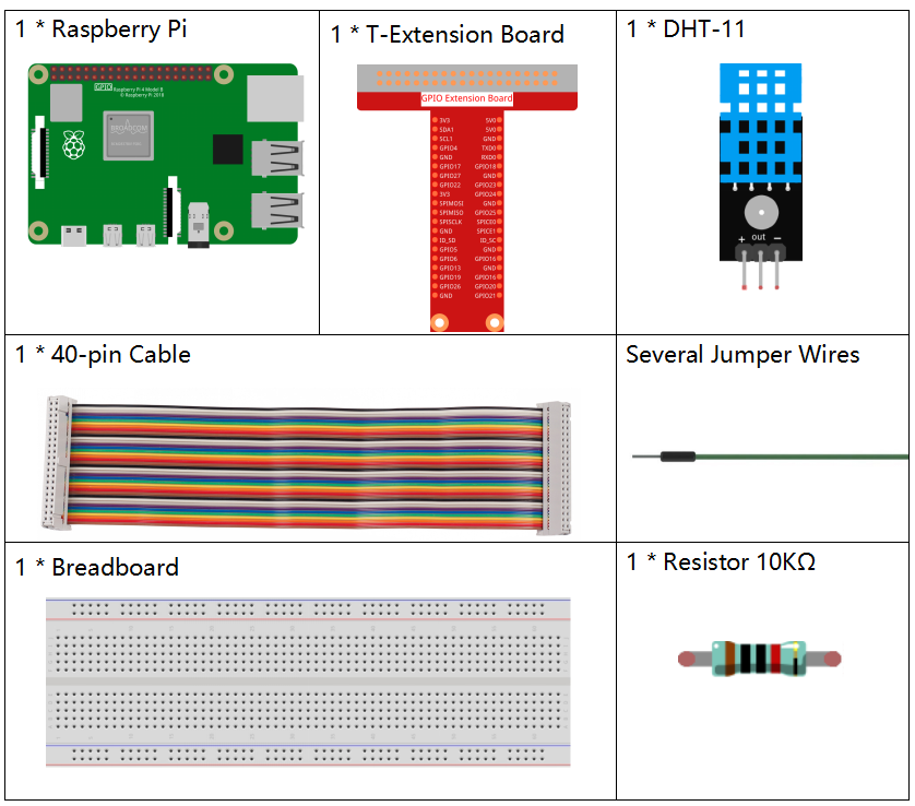
部品
原理
DHT11は基本的な超低コストのデジタル温湿度センサーである。 容量性湿度センサーとサーミスタを使用して周囲の空気を測定し、 データピンにデジタル信号を出力する(アナログ入力ピンは不要)。
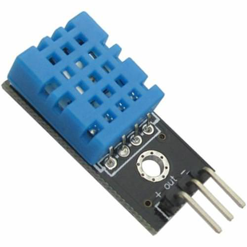
VCC、GND、とDATAの三つのピンのみが利用できる。 通信プロセスは開始信号をDHT11に送信するDATAラインから始まり、 DHT11は信号を受信して応答信号を返す。次に、ホストは応答信号を受信し、 40ビットの湿度データ(8ビット湿度整数+ 8ビット湿度10進数+ 8ビット温度整数+ 8ビット温度10進数+ 8ビットチェックサム)の受信を開始する。 詳細については、DHT11データシートを参照してください。
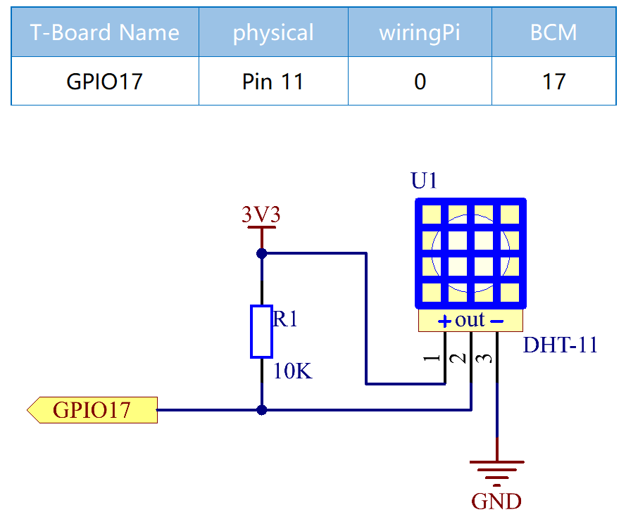
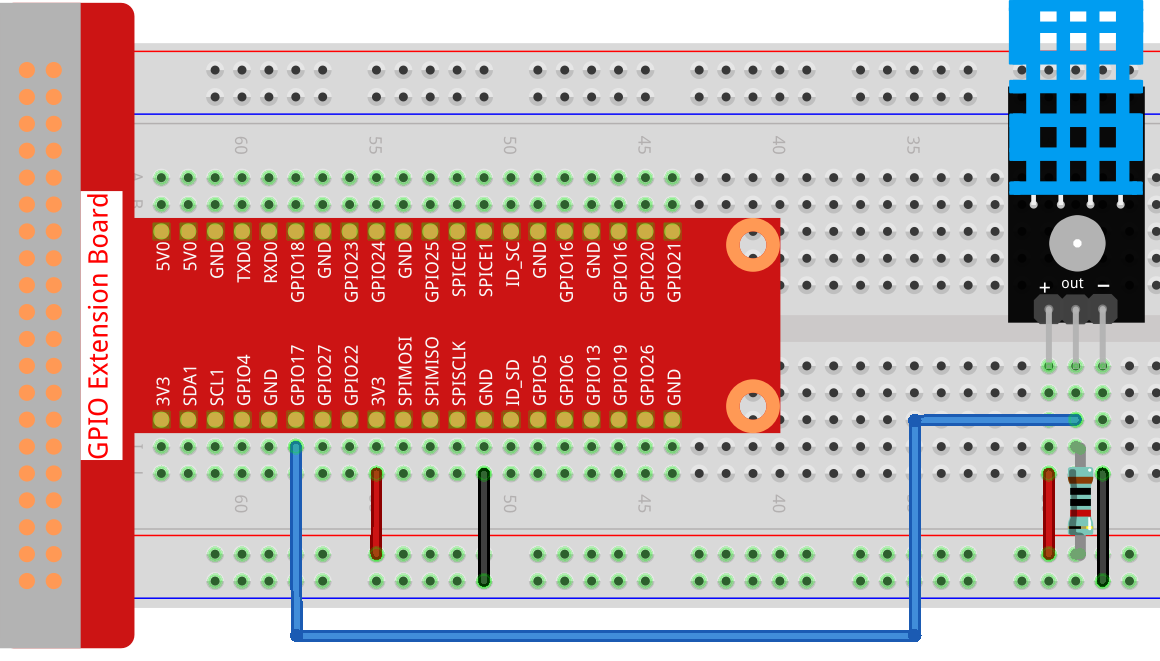
回路図
実験手順
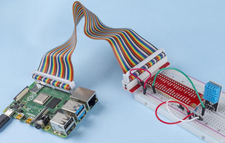
ステップ1: 回路を作る。
C言語ユーザー向け
ステップ2: コードのフォルダーに入る。
cd ~/davinci-kit-for-raspberry-pi/c/2.2.3/
ステップ3: コードをコンパイルする。
gcc 2.2.3_DHT.c -lwiringPi
ステップ4: EXEファイルを実行する。
sudo ./a.out
コードの実行後、プログラムはDHT11によって検出された温度と湿度をコンピューター画面にプリントする。
コード
#include <wiringPi.h>
#include <stdio.h>
#include <stdlib.h>
#include <stdint.h>

#define MAXTIMINGS 85  // Maximum number of timing transitions

int dht11_dat[5] = {0, 0, 0, 0, 0};  // Data array to hold sensor values

// Function to read data from DHT11 sensor
void read_dht11_dat(int GPIOPIN)
{
    uint8_t currState;
    uint8_t laststate = HIGH;
    uint8_t counter = 0;
    uint8_t j = 0;
    uint8_t i;
    float f; // Temperature in Fahrenheit

    // Reset data array before each read
    dht11_dat[0] = dht11_dat[1] = dht11_dat[2] = dht11_dat[3] = dht11_dat[4] = 0;

    // Pull pin down for 18 milliseconds to initiate communication
    pinMode(GPIOPIN, OUTPUT);
    digitalWrite(GPIOPIN, LOW);
    delay(18);

    // Then pull it up for 40 microseconds
    digitalWrite(GPIOPIN, HIGH);
    delayMicroseconds(40);

    // Prepare to read the pin
    pinMode(GPIOPIN, INPUT);

    // Detect change and read data
    for (i = 0; i < MAXTIMINGS; i++)
    {
        counter = 0;

        // Count how long each state lasts
        while (digitalRead(GPIOPIN) == laststate)
        {
            counter++;
            delayMicroseconds(2);
            if (counter == 255)
            {
                break;
            }
        }

        // Save the current state
        laststate = digitalRead(GPIOPIN);

        if (counter == 255) break;

        // Ignore first 3 transitions (DHT11 response signal)
        if ((i >= 4) && (i % 2 == 0))
        {
            // Shift bits and store data
            dht11_dat[j/8] <<= 1;
            if (counter > 16)
            {
                dht11_dat[j/8] |= 1;
            }

            j++;
        }
    }

    // Check if we received 40 bits (5 bytes) and verify checksum
    if ((j >= 40) && (dht11_dat[4] == ((dht11_dat[0] + dht11_dat[1] + dht11_dat[2] + dht11_dat[3]) & 0xFF)) )
    {
        // Convert temperature to Fahrenheit
        f = dht11_dat[2] * 9.0 / 5.0 + 32;
        printf("Humidity = %d.%d %% Temperature = %d.%d °C (%.1f °F)\n",
               dht11_dat[0], dht11_dat[1], dht11_dat[2], dht11_dat[3], f);
    }
    else
    {
        printf("Data not good, skip\n");
    }
}

int main (void)
{
    printf("Raspberry Pi wiringPi DHT11 Temperature test program\n");

    // Initialize wiringPi using BCM GPIO pin numbering
    if (wiringPiSetupGpio() == -1)
    {
        exit(1);
    }

    while(1)
    {
        // Read data from DHT11 connected to GPIO pin 17
        read_dht11_dat(17);
        delay(1000); // Wait 1 second before next read
    }

    return 0;
}
コード説明
ヘッダーのインクルード: コードには、wiringPi関数と標準入出力に必要なヘッダーが含まれています。
#include <wiringPi.h>
#include <stdio.h>
#include <stdlib.h>
#include <stdint.h>
定義:
MAXTIMINGS: DHT11 センサーから予期される最大タイミング遷移数(85)。
#define MAXTIMINGS 85 // Maximum number of timing transitions
グローバルデータ配列:
dht11_dat[5]: DHT11 センサーから受信した 5 バイトのデータを格納する配列。
int dht11_dat[5] = {0, 0, 0, 0, 0}; // Data array to hold sensor values
関数
read_dht11_dat(int GPIOPIN): 指定した GPIO ピンに接続された DHT11 センサーからデータを読み取ります。初期化: 各読み取り前に
dht11_dat配列をゼロにリセットします。dht11_dat[0] = dht11_dat[1] = dht11_dat[2] = dht11_dat[3] = dht11_dat[4] = 0;
スタート信号: DHT11 にデータ送信を開始するように信号を送るために、GPIO ピンを少なくとも 18 ミリ秒間低にします。
pinMode(GPIOPIN, OUTPUT);
digitalWrite(GPIOPIN, LOW);
delay(18);  // 18 milliseconds
GPIO ピンを 40 マイクロ秒間高にします。
digitalWrite(GPIOPIN, HIGH);
delayMicroseconds(40);  // 40 microseconds
センサーからのデータを読み取るために GPIO ピンを入力モードに設定します。
pinMode(GPIOPIN, INPUT);
データ読み取りループ:
MAXTIMINGS回までループしてデータビットを読み取ります。各遷移(高から低、または低から高)に対して、ピンが各状態に滞在する時間を測定します。
for (i = 0; i < MAXTIMINGS; i++)
{
    counter = 0;
    while (digitalRead(GPIOPIN) == laststate)
    {
        counter++;
        delayMicroseconds(2);
        if (counter == 255)
        {
            break;
        }
    }
    laststate = digitalRead(GPIOPIN);
    // ... rest of the loop
}
データビット抽出: 最初の 3 つの遷移は、DHT11 の初期応答の一部であるため無視されます。
各データビットについて、ピンが高状態に滞在する期間に基づいてビットが 0 か 1 かを判定します。
if ((i >= 4) && (i % 2 == 0))
{
    dht11_dat[j/8] <<= 1;
    if (counter > 16)
    {
        dht11_dat[j/8] |= 1;
    }
    j++;
}
チェックサム検証: すべてのビットを受信後、データの整合性を保証するためにチェックサムを検証します。
if ((j >= 40) && (dht11_dat[4] == ((dht11_dat[0] + dht11_dat[1] + dht11_dat[2] + dht11_dat[3]) & 0xFF)) )
チェックサムが正しい場合、湿度および温度の値を出力します。
f = dht11_dat[2] * 9.0 / 5.0 + 32;
printf("Humidity = %d.%d %% Temperature = %d.%d °C (%.1f °F)\n",
       dht11_dat[0], dht11_dat[1], dht11_dat[2], dht11_dat[3], f);
チェックサムが一致しない場合、エラーメッセージを出力します。
else
{
    printf("Data not good, skip\n");
}
メイン関数:
スタートメッセージを出力します。
printf("Raspberry Pi wiringPi DHT11 Temperature test program\n");
BCM GPIO ピン番号を使用して WiringPi を初期化します。
if (wiringPiSetupGpio() == -1)
{
    exit(1);
}
DHT11 センサーから毎秒データを読み取る無限ループに入ります。
while(1)
{
    read_dht11_dat(17);
    delay(1000); // wait 1 second
}
Python言語ユーザー向け
ステップ2: コードのフォルダーに入る。
cd ~/davinci-kit-for-raspberry-pi/python/
ステップ3: EXEファイルを実行する。
sudo python3 2.2.3_DHT.py
コードの実行後、プログラムはDHT11によって検出された温度と湿度をコンピューター画面にプリントする。
コード
注釈
以下のコードを 変更/リセット/コピー/実行/停止 できます。 ただし、その前に、 davinci-kit-for-raspberry-pi/python のようなソースコードパスに移動する必要があります。
from gpiozero import OutputDevice, InputDevice
import time

class DHT11():
   MAX_DELAY_COUINT = 100
   BIT_1_DELAY_COUNT = 10
   BITS_LEN = 40

   def __init__(self, pin, pull_up=False):
      self._pin = pin
      self._pull_up = pull_up


   def read_data(self):
      bit_count = 0
      delay_count = 0
      bits = ""

      # -------------- send start --------------
      gpio = OutputDevice(self._pin)
      gpio.off()
      time.sleep(0.02)

      gpio.close()
      gpio = InputDevice(self._pin, pull_up=self._pull_up)

      # -------------- wait response --------------
      while gpio.value == 1:
            pass

      # -------------- read data --------------
      while bit_count < self.BITS_LEN:
            while gpio.value == 0:
               pass

            # st = time.time()
            while gpio.value == 1:
               delay_count += 1
               # break
               if delay_count > self.MAX_DELAY_COUINT:
                  break
            if delay_count > self.BIT_1_DELAY_COUNT:
               bits += "1"
            else:
               bits += "0"

            delay_count = 0
            bit_count += 1

      # -------------- verify --------------
      humidity_integer = int(bits[0:8], 2)
      humidity_decimal = int(bits[8:16], 2)
      temperature_integer = int(bits[16:24], 2)
      temperature_decimal = int(bits[24:32], 2)
      check_sum = int(bits[32:40], 2)

      _sum = humidity_integer + humidity_decimal + temperature_integer + temperature_decimal

      if check_sum != _sum:
            humidity = 0.0
            temperature = 0.0
      else:
            humidity = float(f'{humidity_integer}.{humidity_decimal}')
            temperature = float(f'{temperature_integer}.{temperature_decimal}')

      # -------------- return --------------
      return humidity, temperature


if __name__ == '__main__':
   dht11 = DHT11(17)
   while True:
      humidity, temperature = dht11.read_data()
      print(f"{time.time():.3f}  temperature:{temperature}°C  humidity: {humidity}%")
      time.sleep(2)
コードの説明
def read_data(self):
   bit_count = 0
   delay_count = 0
   bits = ""

   # -------------- send start --------------
   gpio = OutputDevice(self._pin)
   gpio.off()
   time.sleep(0.02)

   gpio.close()
   gpio = InputDevice(self._pin, pull_up=self._pull_up)
   #...
この関数はDHT11の関数を実装するために使用される。それは検出されたデータを bits[] 配列に保存する。
DHT11は一度に40ビットのデータを点灯する。
最初の16ビットは湿度に関連し、中央の16ビットは温度に関連し、最後の8ビットは検証に使用される。
データ形式は次のとおりである:
8ビット湿度整数データ +8ビット湿度10進データ +8ビット温度整数データ + 8ビット温度10進データ + 8ビットチェックビット。
チェックビットを介して有効性が検出されると、関数は2つの結果を返す:1. エラー; 2.湿度と温度。
_sum = humidity_integer + humidity_decimal + temperature_integer + temperature_decimal

if check_sum != _sum:
      humidity = 0.0
      temperature = 0.0
else:
      humidity = float(f'{humidity_integer}.{humidity_decimal}')
      temperature = float(f'{temperature_integer}.{temperature_decimal}')
たとえば、受信した日付が00101011(湿度整数の8ビット値)00000000(湿度10進数の8ビット値)00111100(温度整数の8ビット値)00000000(温度10進数の8ビット値)01100111(チェックビット)の場合
計算:
00101011+00000000+00111100+00000000=01100111.
最終結果がチェックビットデータと等しい場合、データ送信は異常である:Falseを返す。
最終結果がチェックビットデータと等しく、受信データは正しい場合、
humidity と temperature が返され、「Humidity = 43%、Temperature= 60C」が出力される。
現象画像