注釈
こんにちは、SunFounder Raspberry Pi & Arduino & ESP32 愛好者コミュニティ(Facebook)へようこそ!Raspberry Pi、Arduino、ESP32 をさらに深く学び、仲間と交流しましょう。
参加する理由
専門的な支援: 購入後の問題や技術的な課題を、コミュニティやチームの助けで解決できます。
学びと共有: 技術や工夫を交換し、知識を広げることができます。
限定の先行情報: 新製品のお知らせや先行公開をいち早く入手できます。
特別割引: 最新製品を会員限定の割引で入手できます。
祭りや贈り物企画: 季節ごとの企画や贈り物イベントに参加できます。
👉 一緒に探求し、ものづくりを楽しみましょう!こちらから参加してください → [ここ]
2.1.6 ジョイスティック (MCP3008)
注釈
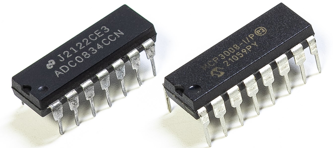
キットの種類によって ADC0834 または MCP3008 が含まれています。必ず手元の部品を確認し、対応する章に進んでください。
はじめに
この章ではジョイスティックの仕組みを学びます。ジョイスティックを操作し、その値を画面に表示します。
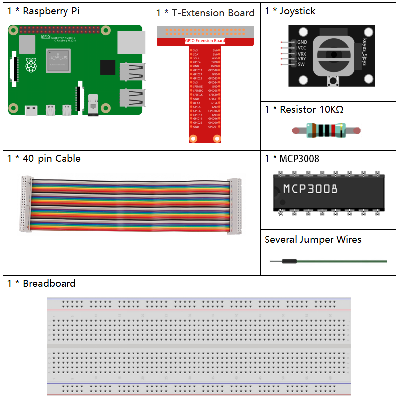
必要な部品
原理
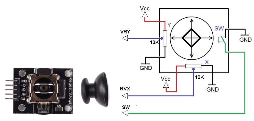
ジョイスティック
ジョイスティックの基本は、棒の動きを電子的な情報に変換し、計算機で処理できるようにすることです。 ジョイスティックは X軸(左右)と Y軸(上下)の二つの軸で動きを検出し、座標として位置を表します。
位置の検出には通常、二つの可変抵抗器を用います。さらにジョイスティックを押し込むと反応するデジタル入力も備わっています。
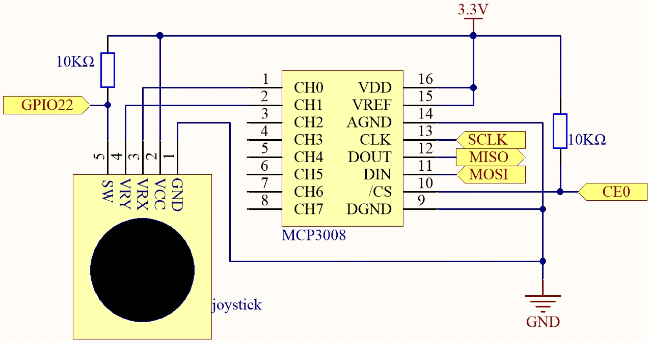
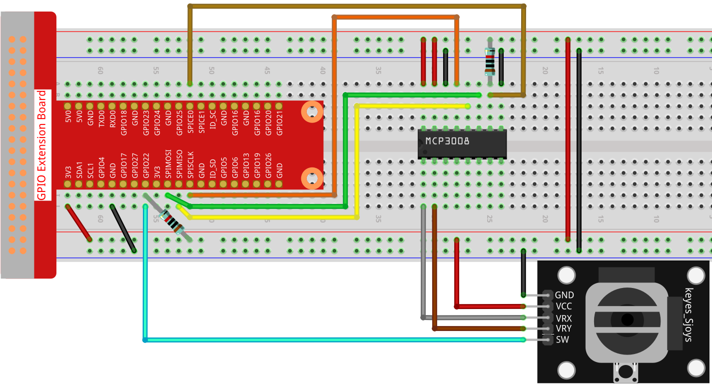
回路図
ジョイスティックのデータは軸ごとに異なります。X軸とY軸はアナログ信号なので MCP3008 を通じてデジタルに変換します。Z軸(押し込み)はデジタル信号なので GPIO から直接読むことができます。
実験手順
手順1: 回路を組みます。
C言語の場合
手順2: コードのあるフォルダに移動します。
cd ~/davinci-kit-for-raspberry-pi/c/2.1.6-2/
手順3: コンパイルします。
gcc 2.1.6_Joystick.c -o joystick -lwiringPi
手順4: 実行します。
./joystick
実行すると、ジョイスティックを動かすことで X, Y, ボタン の値が画面に表示されます。
注釈
「wiringPi.h が見つかりません」というエラーが出た場合は wiringPi のインストールと確認 を参照してください。
コード
#include <wiringPi.h>
#include <wiringPiSPI.h>
#include <stdio.h>

#define SPI_CHANNEL 0
#define SPI_SPEED   1000000  // 1 MHz
#define BtnPin      3        // WiringPi 3 = BCM GPIO22

int read_ADC(int channel) {
    if (channel < 0 || channel > 7) return -1;

    unsigned char buffer[3];
    buffer[0] = 1;
    buffer[1] = (8 + channel) << 4;
    buffer[2] = 0;

    wiringPiSPIDataRW(SPI_CHANNEL, buffer, 3);

    int result = ((buffer[1] & 0x03) << 8) | buffer[2];
    return result;
}

int main(void) {
    if (wiringPiSetup() == -1) {
        printf("WiringPi 初期化失敗!\n");
        return 1;
    }

    if (wiringPiSPISetup(SPI_CHANNEL, SPI_SPEED) == -1) {
        printf("SPI 初期化失敗!\n");
        return 1;
    }

    pinMode(BtnPin, INPUT);
    pullUpDnControl(BtnPin, PUD_UP);

    while (1) {
        int x_val = read_ADC(0);
        int y_val = read_ADC(1);
        int btn_val = digitalRead(BtnPin);

        printf("x = %d, y = %d, btn = %d\n", x_val, y_val, btn_val);
        delay(100);
    }

    return 0;
}
コード解説
GPIO と SPI 通信に必要なライブラリを読み込みます。
#include <wiringPi.h>
#include <wiringPiSPI.h>
#include <stdio.h>

#define SPI_CHANNEL 0
#define SPI_SPEED   1000000
#define BtnPin      3
read_ADC()関数で MCP3008 からアナログ値を読み取ります。指定したチャンネルに対して SPI で通信し、10ビットの値を返します。int read_ADC(int channel) { if (channel < 0 || channel > 7) return -1; unsigned char buffer[3]; buffer[0] = 1; buffer[1] = (8 + channel) << 4; buffer[2] = 0; wiringPiSPIDataRW(SPI_CHANNEL, buffer, 3); int result = ((buffer[1] & 0x03) << 8) | buffer[2]; return result; }
main関数では WiringPi と SPI を初期化し、ボタン入力ピンを設定します。ループの中でジョイスティックの X, Y 値とボタン状態を読み取り、画面に表示します。int main(void) { if (wiringPiSetup() == -1) { printf("WiringPi setup failed!\n"); return 1; } if (wiringPiSPISetup(SPI_CHANNEL, SPI_SPEED) == -1) { printf("SPI setup failed!\n"); return 1; } pinMode(BtnPin, INPUT); pullUpDnControl(BtnPin, PUD_UP); while (1) { int x_val = read_ADC(0); // VRX to CH0 int y_val = read_ADC(1); // VRY to CH1 int btn_val = digitalRead(BtnPin); // SW to GPIO22 printf("x = %d, y = %d, btn = %d\n", x_val, y_val, btn_val); delay(100); } return 0; }
Pythonの場合
手順2: SPI を設定し、 spidev をインストールしてください(詳細は SPI 設定 を参照)。
手順3: コードのあるフォルダに移動します。
cd ~/davinci-kit-for-raspberry-pi/python
手順4: 実行します。
sudo python3 2.1.6-2_Joystick.py
実行すると、ジョイスティックを動かすことで X, Y, ボタン の値が画面に表示されます。
警告
RuntimeError: Cannot determine SOC peripheral base address というエラーが出た場合は 「gpiozero」が動作しない場合。 を参照してください。
コード
#!/usr/bin/env python3

import RPi.GPIO as GPIO
import spidev
import time

BTN_PIN = 22

GPIO.setmode(GPIO.BCM)
GPIO.setup(BTN_PIN, GPIO.IN, pull_up_down=GPIO.PUD_UP)

spi = spidev.SpiDev()
spi.open(0, 0)
spi.max_speed_hz = 1000000

def read_adc(channel):
    if channel < 0 or channel > 7:
        return -1
    adc = spi.xfer2([1, (8 + channel) << 4, 0])
    value = ((adc[1] & 0x03) << 8) | adc[2]
    return value

try:
    while True:
        x_val = read_adc(1)
        y_val = read_adc(2)
        Btn_val = GPIO.input(BTN_PIN)

        print('X: %d  Y: %d  Btn: %d' % (x_val, y_val, Btn_val))
        time.sleep(0.2)

except KeyboardInterrupt:
    pass

finally:
    spi.close()
    GPIO.cleanup()
コード解説
必要なライブラリを読み込みます。
RPi.GPIO: ボタン入力の制御spidev: MCP3008 と SPI 通信time: 待機処理
#!/usr/bin/env python3

import RPi.GPIO as GPIO
import spidev
import time
GPIO22 を内部プルアップ付きで入力に設定し、SPI を初期化します。
# Define GPIO pin for joystick button (SW pin)
BTN_PIN = 22

# Set up GPIO mode
GPIO.setmode(GPIO.BCM)
GPIO.setup(BTN_PIN, GPIO.IN, pull_up_down=GPIO.PUD_UP)

# Initialize SPI communication with MCP3008
spi = spidev.SpiDev()
spi.open(0, 0)  # SPI bus 0, CE0
spi.max_speed_hz = 1000000
read_adc()関数で MCP3008 の指定チャンネルから値を取得し、0–1023 の範囲で返します。def read_adc(channel): """ Reads analog value from the specified MCP3008 channel (0–7) :param channel: ADC channel number (0–7) :return: 10-bit integer value (0–1023) """ if channel < 0 or channel > 7: return -1 adc = spi.xfer2([1, (8 + channel) << 4, 0]) value = ((adc[1] & 0x03) << 8) | adc[2] return value
メインループでは X, Y のアナログ値とボタン状態を読み取り、200ms ごとに表示します。Ctrl+C で中断すると SPI と GPIO を解放して終了します。
try:
   # Main loop to read and print joystick values and button state
   while True:
         # Read X and Y values from MCP3008 channels 0 and 1
         x_val = read_adc(0)  # Joystick VRX connected to CH0
         y_val = read_adc(1)  # Joystick VRY connected to CH1

         # Read the state of the joystick button (SW)
         Btn_val = GPIO.input(BTN_PIN)  # 0 = pressed, 1 = released

         # Print the read values
         print('X: %d  Y: %d  Btn: %d' % (x_val, y_val, Btn_val))

         time.sleep(0.2)

except KeyboardInterrupt:
   pass

finally:
   spi.close()
   GPIO.cleanup()