Nota
Ciao, benvenuto nella Community di appassionati SunFounder Raspberry Pi & Arduino & ESP32 su Facebook! Approfondisci Raspberry Pi, Arduino ed ESP32 insieme ad altri appassionati.
Perché unirsi?
Supporto esperto: risolvi problemi post-vendita e sfide tecniche con l’aiuto della community e del nostro team.
Impara e condividi: scambia consigli e tutorial per migliorare le tue competenze.
Anteprime esclusive: ottieni accesso anticipato a nuovi annunci di prodotto e anteprime.
Sconti speciali: usufruisci di sconti esclusivi sui nostri prodotti più recenti.
Promozioni festive e giveaway: partecipa a giveaway e promozioni durante le festività.
👉 Pronto a esplorare e creare con noi? Clicca [Qui] e unisciti oggi!
3.1.8 Monitor di Surriscaldamento (MCP3008)
Nota
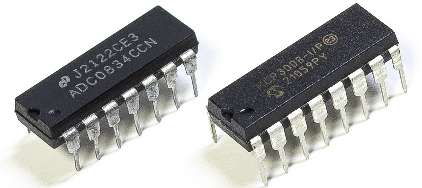
A seconda della versione del kit, identifica se hai ADC0834 o MCP3008 e procedi con la sezione corrispondente.
Introduzione
Potresti voler realizzare un dispositivo di monitoraggio del surriscaldamento applicabile a varie situazioni, ad esempio in fabbrica, quando vogliamo avere un allarme e lo spegnimento automatico tempestivo della macchina in caso di surriscaldamento di un circuito. In questo progetto utilizzeremo termistore, joystick, buzzer, LED e LCD per creare un dispositivo intelligente di monitoraggio della temperatura con soglia regolabile.
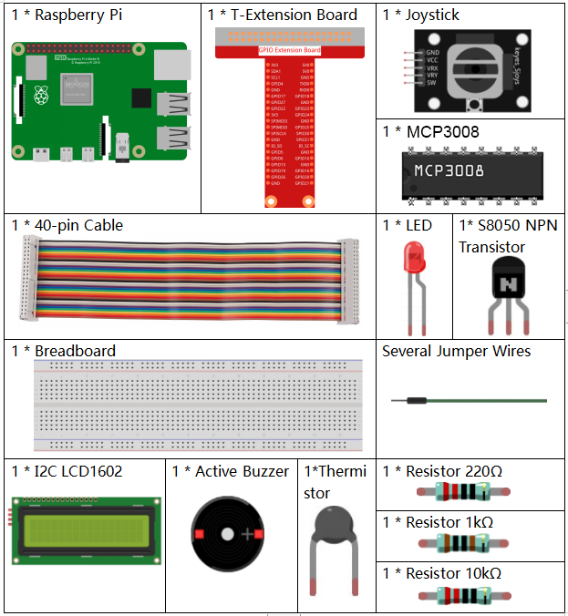
Componenti necessari
In questo progetto, abbiamo bisogno dei seguenti componenti.
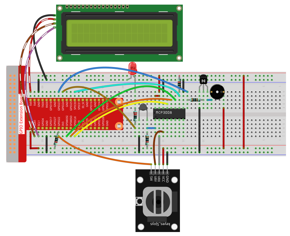
Schema elettrico
T-Board Name |
physical |
wiringPi |
BCM |
SPICE0 |
Pin 24 |
10 |
8 |
SPIMOSI |
Pin 19 |
12 |
10 |
SPIMISO |
Pin 21 |
13 |
9 |
SPISCLK |
Pin 23 |
14 |
11 |
GPIO22 |
Pin15 |
3 |
22 |
GPIO23 |
Pin16 |
4 |
23 |
GPIO24 |
Pin18 |
5 |
24 |
SDA1 |
Pin 3 |
||
SCL1 |
Pin 5 |

Procedure sperimentali
Passo 1: Monta il circuito.
Per utenti C Language
Passo 2: Vai nella cartella del codice.
cd ~/davinci-kit-for-raspberry-pi/c/3.1.8-2/
Passo 3: Compila il codice.
gcc 3.1.8_OverheatMonitor.c -lm -lwiringPi
Passo 4: Esegui il file compilato.
sudo ./a.out
Quando il codice è in esecuzione, la temperatura attuale e la soglia di alta temperatura 40 vengono visualizzate su I2C LCD1602. Se la temperatura attuale è maggiore della soglia, buzzer e LED si attivano per avvisarti.
Il joystick serve per regolare la soglia di temperatura alta. Spostandolo sugli assi X e Y puoi aumentare o diminuire la soglia. Premendo di nuovo il joystick la soglia si resetta al valore iniziale.
Nota
Se appare l’errore
wiringPi.h: No such file or directory, fare riferimento a Installare e Verificare WiringPi.Se appare
Unable to open I2C device: No such file or directory, fare riferimento a Configurazione I²C per abilitare l’I2C e controllare il cablaggio.Se il codice e il cablaggio sono corretti ma l’LCD non mostra nulla, regolare il potenziometro sul retro per aumentare il contrasto.
Code
#include <wiringPi.h>
#include <stdio.h>
#include <wiringPiI2C.h>
#include <wiringPiSPI.h>
#include <string.h>
#include <math.h>

typedef unsigned char uchar;
typedef unsigned int  uint;

#define Joy_BtnPin 3      // GPIO22 -> WiringPi 3
#define buzzPin    4      // GPIO23 -> WiringPi 4
#define LedPin     5      // GPIO24 -> WiringPi 5
#define SPI_CHANNEL 0
#define SPI_SPEED   1000000

int LCDAddr    = 0x27;
int BLEN       = 1;
int fd;
int upperTem   = 40;

// Global variable to store the last joystick change
int lastJoystickChange = 0;

int read_ADC(int channel) {
    if (channel < 0 || channel > 7) return -1;
    unsigned char buffer[3];
    buffer[0] = 1;
    buffer[1] = (8 + channel) << 4;
    buffer[2] = 0;
    wiringPiSPIDataRW(SPI_CHANNEL, buffer, 3);
    return ((buffer[1] & 0x03) << 8) | buffer[2];
}

void write_word(int data){
    int temp = data;
    if (BLEN)      temp |= 0x08;
    else           temp &= 0xF7;
    wiringPiI2CWrite(fd, temp);
}

void send_command(int comm){
    int buf = comm & 0xF0;
    buf |= 0x04; write_word(buf); delay(2); buf &= 0xFB; write_word(buf);
    buf = (comm & 0x0F) << 4;
    buf |= 0x04; write_word(buf); delay(2); buf &= 0xFB; write_word(buf);
}

void send_data(int data){
    int buf = data & 0xF0;
    buf |= 0x05; write_word(buf); delay(2); buf &= 0xFB; write_word(buf);
    buf = (data & 0x0F) << 4;
    buf |= 0x05; write_word(buf); delay(2); buf &= 0xFB; write_word(buf);
}

void lcd_init(){
    send_command(0x33); delay(5);
    send_command(0x32); delay(5);
    send_command(0x28); delay(5);
    send_command(0x0C); delay(5);
    send_command(0x01); wiringPiI2CWrite(fd, 0x08);
}

void lcd_clear(){
    send_command(0x01);
}

void write_lcd(int x, int y, const char data[]){
    int addr = 0x80 + 0x40 * y + x;
    send_command(addr);
    for (int i = 0; i < (int)strlen(data); i++)
        send_data(data[i]);
}

int get_joystick_value(){
    int x = read_ADC(1);
    int y = read_ADC(2);

    // Dead-band filtering to reduce small fluctuations
    if (x > 900)      return  1;   //    else if (x < 100) return -1;   //     else if (y > 900) return -10;  //     else if (y < 100) return  10;  //    else              return   0;
}

void upper_tem_setting(){
    write_lcd(0,0, "Upper Adjust:");

    int change = get_joystick_value();

    // Only respond to actual direction change
    if (change != 0 && change != lastJoystickChange) {
        upperTem += change;
        lastJoystickChange = change;
    }
    else if (change == 0) {
        // Allow next change after returning to center
        lastJoystickChange = 0;
    }

    // Display current upperTem
    char str[6];
    snprintf(str, sizeof(str), "%d", upperTem);
    write_lcd(0,1, str);
    // Clear remaining LCD characters
    write_lcd(strlen(str),1, "            ");

    delay(100);
}

double temperature(){
    int raw = read_ADC(0);
    double Vr = 3.3 * ((double)raw / 1023.0);
    double Rt = 10000.0 * Vr / (3.3 - Vr);
    double tempK = 1.0 / ((log(Rt/10000.0)/3950.0) + 1.0/(273.15+25.0));
    return tempK - 273.15;
}

void monitoring_temp(){
    char str[6];
    double cel = temperature();
    snprintf(str, sizeof(str), "%.2f", cel);
    write_lcd(0,0, "Temp: ");
    write_lcd(6,0, str);

    snprintf(str, sizeof(str), "%d", upperTem);
    write_lcd(0,1, "Upper: ");
    write_lcd(7,1, str);
    delay(100);

    if (cel >= upperTem) {
        digitalWrite(buzzPin, HIGH);
        digitalWrite(LedPin,  HIGH);
    } else {
        digitalWrite(buzzPin, LOW);
        digitalWrite(LedPin,  LOW);
    }
}

void setup_all(){
    fd = wiringPiI2CSetup(LCDAddr);
    lcd_init();
    if (wiringPiSetup() == -1 ||
        wiringPiSPISetup(SPI_CHANNEL, SPI_SPEED) == -1) {
        printf("Setup failed!\n");
        return;
    }
    pinMode(Joy_BtnPin, INPUT);
    pullUpDnControl(Joy_BtnPin, PUD_UP);
    pinMode(buzzPin, OUTPUT);
    pinMode(LedPin,  OUTPUT);
}

int main(void){
    setup_all();

    int lastBtnState = HIGH;
    int stage = 0;

    while (1) {
        int curBtn = digitalRead(Joy_BtnPin);
        // Switch mode when button changes from LOW to HIGH (button released)
        if (curBtn == HIGH && lastBtnState == LOW) {
            stage = (stage + 1) % 2;
            lastJoystickChange = 0;  // Clear debounce status
            delay(100);
            lcd_clear();
        }
        lastBtnState = curBtn;

        if (stage == 1)
            upper_tem_setting();
        else
            monitoring_temp();
    }

    return 0;
}
Spiegazione del codice
int read_ADC(int channel) {
    if (channel < 0 || channel > 7) return -1;
    unsigned char buffer[3];
    buffer[0] = 1;
    buffer[1] = (8 + channel) << 4;
    buffer[2] = 0;
    wiringPiSPIDataRW(SPI_CHANNEL, buffer, 3);
    return ((buffer[1] & 0x03) << 8) | buffer[2];
}
Legge un valore analogico a 10 bit dal canale MCP3008 (CH0–CH7) tramite SPI e restituisce un intero da 0 a 1023.
int get_joystick_value() {
    int x = read_ADC(1);
    int y = read_ADC(2);

    if (x > 900)      return 1;   // Destra
    else if (x < 100) return -1;  // Sinistra
    else if (y > 900) return -10; // Su
    else if (y < 100) return 10;  // Giù
    else              return 0;
}
Legge i valori analogici X e Y del joystick dai canali CH1 e CH2. Restituisce un intero che indica la direzione di movimento in base alle soglie.
void upper_tem_setting() {
    write_lcd(0,0, "Upper Adjust:");

    int change = get_joystick_value();

    if (change != 0 && change != lastJoystickChange) {
        upperTem += change;
        lastJoystickChange = change;
    }
    else if (change == 0) {
        lastJoystickChange = 0;
    }

    char str[6];
    snprintf(str, sizeof(str), "%d", upperTem);
    write_lcd(0,1, str);
    write_lcd(strlen(str),1, "            ");

    delay(100);
}
Permette all’utente di regolare la soglia di temperatura massima con il joystick, evitando modifiche ripetute se la direzione viene mantenuta.
double temperature() {
    int raw = read_ADC(0);
    double Vr = 3.3 * ((double)raw / 1023.0);
    double Rt = 10000.0 * Vr / (3.3 - Vr);
    double tempK = 1.0 / ((log(Rt/10000.0)/3950.0) + 1.0/(273.15+25.0));
    return tempK - 273.15;
}
Legge il valore analogico dal CH0 collegato al termistore. Usa l’equazione di Steinhart–Hart per calcolare la temperatura in gradi Celsius.
void monitoring_temp() {
    char str[6];
    double cel = temperature();
    snprintf(str, sizeof(str), "%.2f", cel);
    write_lcd(0,0, "Temp: ");
    write_lcd(6,0, str);

    snprintf(str, sizeof(str), "%d", upperTem);
    write_lcd(0,1, "Upper: ");
    write_lcd(7,1, str);
    delay(100);

    if (cel >= upperTem) {
        digitalWrite(buzzPin, HIGH);
        digitalWrite(LedPin,  HIGH);
    } else {
        digitalWrite(buzzPin, LOW);
        digitalWrite(LedPin,  LOW);
    }
}
Legge continuamente la temperatura attuale e la visualizza insieme alla soglia. Se la temperatura supera la soglia, il buzzer e il LED si attivano.
void setup_all() {
    fd = wiringPiI2CSetup(LCDAddr);
    lcd_init();
    if (wiringPiSetup() == -1 || wiringPiSPISetup(SPI_CHANNEL, SPI_SPEED) == -1) {
        printf("Setup failed!\n");
        return;
    }
    pinMode(Joy_BtnPin, INPUT);
    pullUpDnControl(Joy_BtnPin, PUD_UP);
    pinMode(buzzPin, OUTPUT);
    pinMode(LedPin,  OUTPUT);
}
Inizializza LCD, SPI, GPIO per pulsante del joystick, buzzer e LED. Imposta anche la resistenza di pull-up per il pulsante del joystick.
int main(void) {
    setup_all();

    int lastBtnState = HIGH;
    int stage = 0;

    while (1) {
        int curBtn = digitalRead(Joy_BtnPin);
        if (curBtn == HIGH && lastBtnState == LOW) {
            stage = (stage + 1) % 2;
            lastJoystickChange = 0;
            delay(100);
            lcd_clear();
        }
        lastBtnState = curBtn;

        if (stage == 1)
            upper_tem_setting();
        else
            monitoring_temp();
    }

    return 0;
}
Il ciclo principale alterna tra due modalità:
Monitoraggio della temperatura.
Regolazione del limite superiore tramite joystick.
La modalità cambia quando il pulsante del joystick viene rilasciato (trigger sul fronte di salita).
Per utenti Python Language
Passo 2: Configura l’interfaccia SPI e installa la libreria spidev (vedi Configurazione SPI per le istruzioni dettagliate). Se lo hai già fatto, puoi saltare questo passo.
Passo 3: Vai nella cartella del codice.
cd ~/raphael-kit/python
Passo 4: Esegui il file.
sudo python3 3.1.8-2_OverheatMonitor.py
Quando il codice è in esecuzione, la temperatura attuale e la soglia 40 vengono mostrate su I2C LCD1602. Se la temperatura è maggiore della soglia, buzzer e LED si attivano per avvisarti.
Il joystick permette di regolare la soglia di alta temperatura: spostandolo sugli assi X/Y puoi aumentare o diminuire la soglia; premendolo di nuovo, si resetta al valore iniziale.
Nota
Se appare l’errore
FileNotFoundError: [Errno 2] No such file or directory: '/dev/i2c-1', abilita l’I2C come spiegato in Configurazione I²C.Se appare
ModuleNotFoundError: No module named 'smbus2', eseguisudo apt install python3-smbus2.Se appare
OSError: [Errno 121] Remote I/O error, significa che il modulo è cablato male o difettoso.Se l’LCD non mostra nulla, regola il potenziometro sul retro.
Avvertimento
Se appare l’errore RuntimeError: Cannot determine SOC peripheral base address, vedere Se gpiozero non funziona.
Codice
Nota
Puoi Modificare/Reimpostare/Copiare/Eseguire/Arrestare il codice qui sotto. Prima di farlo, però, devi accedere al percorso del codice sorgente, ad esempio davinci-kit-for-raspberry-pi/python.
#!/usr/bin/env python3

import RPi.GPIO as GPIO
import spidev
import time
import math
import LCD1602

# GPIO pin definitions
JOY_BTN_PIN = 22  # Button pin
BUZZER_PIN = 23   # Buzzer pin
LED_PIN = 24      # LED pin

# Initialize GPIO
GPIO.setmode(GPIO.BCM)
GPIO.setup(JOY_BTN_PIN, GPIO.IN, pull_up_down=GPIO.PUD_UP)
GPIO.setup(BUZZER_PIN, GPIO.OUT)
GPIO.setup(LED_PIN, GPIO.OUT)

# Set initial upper temperature threshold
upperTem = 40

# Initialize SPI for MCP3008
spi = spidev.SpiDev()
spi.open(0, 0)
spi.max_speed_hz = 1000000  # 1 MHz

# Initialize LCD1602
LCD1602.init(0x27, 1)

def read_adc(channel):
    """
    Read analog value from MCP3008 (0–7)
    """
    if channel < 0 or channel > 7:
        return -1
    adc = spi.xfer2([1, (8 + channel) << 4, 0])
    value = ((adc[1] & 0x03) << 8) | adc[2]
    return value

def get_joystick_value():
    """
    Reads the joystick values and returns a change value based on the joystick's position.
    """
    x_val = read_adc(1)
    y_val = read_adc(2)
    if x_val > 800:
        return 1
    elif x_val < 200:
        return -1
    elif y_val > 800:
        return -10
    elif y_val < 200:
        return 10
    else:
        return 0

def upper_tem_setting():
    """
    Adjusts and displays the upper temperature threshold on the LCD.
    """
    global upperTem
    LCD1602.write(0, 0, 'Upper Adjust: ')
    change = int(get_joystick_value())
    upperTem += change
    strUpperTem = str(upperTem)
    LCD1602.write(0, 1, strUpperTem)
    LCD1602.write(len(strUpperTem), 1, '              ')
    time.sleep(0.1)

def temperature():
    """
    Reads the current temperature from the sensor and returns it in Celsius.
    """
    analogVal = read_adc(0)
    Vr = 3.3 * analogVal / 1023.0
    if Vr == 0:
        return 0
    Rt = 10000.0 * (3.3 - Vr) / Vr
    tempK = 1.0 / (((math.log(Rt / 10000.0)) / 3950.0) + (1.0 / (273.15 + 25.0)))
    Cel = tempK - 273.15
    return round(Cel, 2)

def monitoring_temp():
    """
    Monitors and displays the current temperature and upper temperature threshold.
    Activates buzzer and LED if the temperature exceeds the upper limit.
    """
    global upperTem
    Cel = temperature()
    LCD1602.write(0, 0, 'Temp: ')
    LCD1602.write(0, 1, 'Upper: ')
    LCD1602.write(6, 0, str(Cel))
    LCD1602.write(7, 1, str(upperTem))
    time.sleep(0.1)
    if Cel >= upperTem:
        GPIO.output(BUZZER_PIN, GPIO.HIGH)
        GPIO.output(LED_PIN, GPIO.HIGH)
    else:
        GPIO.output(BUZZER_PIN, GPIO.LOW)
        GPIO.output(LED_PIN, GPIO.LOW)

# Main loop
try:
    lastState = GPIO.input(JOY_BTN_PIN)
    stage = 0
    while True:
        currentState = GPIO.input(JOY_BTN_PIN)
        if currentState == GPIO.HIGH and lastState == GPIO.LOW:
            stage = (stage + 1) % 2
            time.sleep(0.1)
            LCD1602.clear()
        lastState = currentState

        if stage == 1:
            upper_tem_setting()
        else:
            monitoring_temp()

except KeyboardInterrupt:
    pass

finally:
    LCD1602.clear()
    GPIO.cleanup()
    spi.close()
Spiegazione del codice
Importazione delle librerie
Questa sezione carica le librerie necessarie per GPIO, SPI, display LCD, ritardi temporali e operazioni matematiche.
#!/usr/bin/env python3
import RPi.GPIO as GPIO
import spidev
import time
import math
import LCD1602
Configurazione dei GPIO e dei dispositivi
Definisce i numeri dei pin GPIO per il pulsante del joystick, il buzzer e il LED, e configura le modalità GPIO.
JOY_BTN_PIN = 22  # Pin pulsante
BUZZER_PIN = 23   # Pin buzzer
LED_PIN = 24      # Pin LED

GPIO.setmode(GPIO.BCM)
GPIO.setup(JOY_BTN_PIN, GPIO.IN, pull_up_down=GPIO.PUD_UP)
GPIO.setup(BUZZER_PIN, GPIO.OUT)
GPIO.setup(LED_PIN, GPIO.OUT)
Inizializzazione di SPI e LCD
Avvia l’interfaccia SPI per MCP3008 e inizializza il display LCD1602 con indirizzo I2C 0x27.
upperTem = 40
spi = spidev.SpiDev()
spi.open(0, 0)
spi.max_speed_hz = 1000000

LCD1602.init(0x27, 1)
Lettura del valore ADC
Legge i dati analogici dall’ADC MCP3008 tramite SPI. Il canale deve essere compreso tra 0 e 7.
def read_adc(channel):
    if channel < 0 or channel > 7:
        return -1
    adc = spi.xfer2([1, (8 + channel) << 4, 0])
    value = ((adc[1] & 0x03) << 8) | adc[2]
    return value
Rilevamento del movimento del joystick
Controlla i valori degli assi X/Y del joystick e restituisce di quanto modificare la soglia.
def get_joystick_value():
    x_val = read_adc(1)
    y_val = read_adc(2)
    if x_val > 800:
        return 1
    elif x_val < 200:
        return -1
    elif y_val > 800:
        return -10
    elif y_val < 200:
        return 10
    else:
        return 0
Regolazione della soglia di temperatura massima
Visualizza “Upper Adjust” sull’LCD e modifica la soglia utilizzando l’input del joystick.
def upper_tem_setting():
    global upperTem
    LCD1602.write(0, 0, 'Upper Adjust: ')
    change = int(get_joystick_value())
    upperTem += change
    strUpperTem = str(upperTem)
    LCD1602.write(0, 1, strUpperTem)
    LCD1602.write(len(strUpperTem), 1, '              ')
    time.sleep(0.1)
Calcolo della temperatura
Converte la lettura analogica del sensore in tensione, poi in resistenza e infine in temperatura (°C) utilizzando l’approssimazione di Steinhart–Hart.
def temperature():
    analogVal = read_adc(0)
    Vr = 3.3 * analogVal / 1023.0
    if Vr == 0:
        return 0
    Rt = 10000.0 * (3.3 - Vr) / Vr
    tempK = 1.0 / (((math.log(Rt / 10000.0)) / 3950.0) + (1.0 / (273.15 + 25.0)))
    Cel = tempK - 273.15
    return round(Cel, 2)
Monitoraggio della temperatura
Controlla e visualizza continuamente la temperatura e il limite massimo. Accende buzzer e LED se la temperatura supera la soglia.
def monitoring_temp():
    global upperTem
    Cel = temperature()
    LCD1602.write(0, 0, 'Temp: ')
    LCD1602.write(0, 1, 'Upper: ')
    LCD1602.write(6, 0, str(Cel))
    LCD1602.write(7, 1, str(upperTem))
    time.sleep(0.1)
    if Cel >= upperTem:
        GPIO.output(BUZZER_PIN, GPIO.HIGH)
        GPIO.output(LED_PIN, GPIO.HIGH)
    else:
        GPIO.output(BUZZER_PIN, GPIO.LOW)
        GPIO.output(LED_PIN, GPIO.LOW)
Logica principale del programma
Alterna tra il monitoraggio della temperatura e la regolazione della soglia quando viene premuto il pulsante del joystick.
try:
    lastState = GPIO.input(JOY_BTN_PIN)
    stage = 0
    while True:
        currentState = GPIO.input(JOY_BTN_PIN)
        if currentState == GPIO.HIGH and lastState == GPIO.LOW:
            stage = (stage + 1) % 2
            time.sleep(0.1)
            LCD1602.clear()
        lastState = currentState

        if stage == 1:
            upper_tem_setting()
        else:
            monitoring_temp()
Pulizia in uscita
Garantisce lo spegnimento corretto delle risorse GPIO e SPI quando si preme Ctrl+C.
except KeyboardInterrupt:
    pass
finally:
    LCD1602.clear()
    GPIO.cleanup()
    spi.close()